
An automotive steering rack is not a plain round shaft. Its toothed zone, smooth journals, end features and sometimes flat or Y-shaped cross-sections create different measuring and contact conditions along a single workpiece. A reliable steering rack straightening solution therefore establishes a functional datum, separates profile geometry from true centreline bend, protects critical surfaces and verifies the final result with the same inspection logic the customer uses.
This page describes a configurable automatic press-straightening process for machined or formed steering racks. It deliberately does not assign one material, size, accuracy or cycle time to every rack: those values come from the drawing, representative samples and an agreed acceptance method.
Rack Geometry Changes the Straightening Problem
| Section | Function | Straightening concern |
|---|---|---|
| Smooth shaft or journal | Guidance, sealing, bearing reference | Valid measuring and contact area only if it matches the drawing datum |
| Toothed rack section | Transfers linear force through rack-and-pinion mesh | Tooth height creates a periodic probe signal; contact must not damage flanks or crests |
| Flat or Y-shaped section | Packaging, stiffness, formed geometry | Cannot be treated as a constant round diameter |
| Threaded or machined end | Assembly interface | May need protected support and a separate runout check |
| Hardened transition | Wear-resistant functional zone | Local stiffness and residual stress differ from the core and adjacent shaft |
Equipment makers publishing on this family treat steering racks as high-accuracy workpieces with asymmetric cross-sections requiring exact gear-tooth measurement, dedicated measuring systems and section-specific anvils and punches. Those references support the need for a profile-specific process; their published figures are not specifications for any machine offered here.
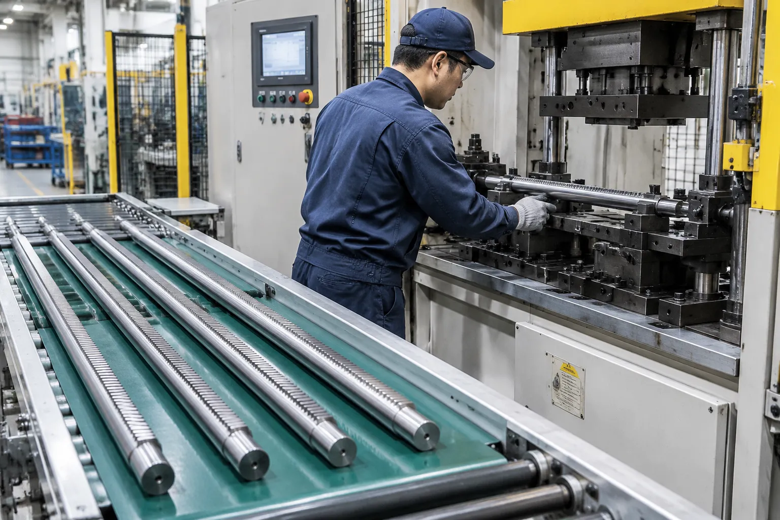
Concept illustration based on a published demonstration video; individual values visible in any single frame are not universal results or machine specifications.
The Automatic Process, Step by Step
1. Identify the variant
The recipe is selected from part number, barcode or data-matrix code and locked to the drawing revision. Where several rack variants share the station, keyed tooling and poka-yoke prevent a recipe running on the wrong fixture.
2. Load and locate on the functional datum
The rack is seated on end locators or supports that reproduce the functional axis without carrying press force through teeth, threads or seal surfaces. Seating is verified before rotation starts.
3. Rotate and measure
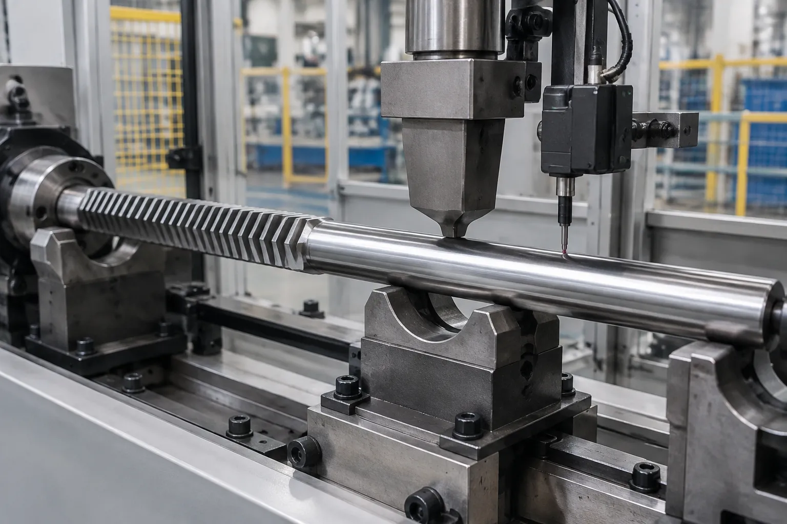
Concept illustration; actual tooling profiles and contact zones are validated per approved rack variant.
Sensors record deviation at drawing-defined stations while the part rotates or indexes. The measurement model is profile-aware: a probe riding teeth must be interpreted against the tooth geometry, or measurement moves to approved smooth reference zones. Readings that fail plausibility checks, dirt, unstable contact, lost angular reference, never become corrections.
4. Select supports and correction point
The controller selects an approved support span and press location for the measured bend. Tooth flanks, seal surfaces, threads and other prohibited areas are excluded by tooling design and recipe limits.
5. Apply staged press correction
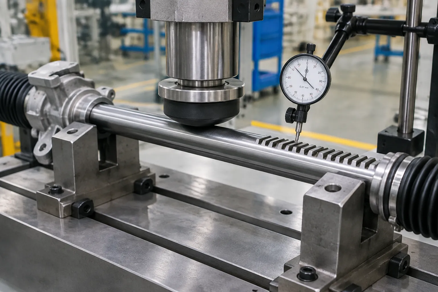
The ram applies controlled displacement or force. Hardened and asymmetric parts respond differently by direction and axial zone, so correction is incremental, with maximum force, stroke and iteration limits preventing uncontrolled repeated loading.
6. Remeasure and iterate
After each correction the part is measured again on the same datum, and another correction happens only when the residual error and the approved process window call for it.
7. Verify and unload
The final result is compared with the drawing-specific acceptance rule. Optional functions, separate OK/NOK discharge, data storage, crack detection, line communication, exist only when they are part of the ordered and validated configuration.
Demonstration Video
The video below shows actual racks, an automatic straightening station and a measurement and control display. It supports the application and process concept; it does not certify every numerical statement on any supplier’s website.
Press Tooling and Surface Protection
For steering racks, “no damage” is an inspection requirement, not a generic machine feature. Tooling is selected for the real cross-section, hardness, coating and permitted contact zones:
| Tooling element | Design question |
|---|---|
| Centres or end locators | Do they reproduce the functional axis without carrying press force improperly? |
| Anvils and supports | Do they match the local section and avoid tooth, thread and seal surfaces? |
| Press punch | Is its radius and profile compatible with the approved contact zone and force? |
| Measuring stylus or shoe | Does it read centreline deviation rather than tooth-gap geometry? |
| Changeover tooling | Is each variant physically keyed and verified before its recipe can run? |
Public equipment references show the market answering the same questions: section-specific anvils and punches, optional crack detection, and pressure straightening named as the appropriate approach for slim, special-cross-section, crack-sensitive components. Those references justify putting surface and crack inspection in the feasibility plan; they never justify claiming damage is impossible.
Sample Test and Acceptance Plan
Representative samples
- normal production parts spanning the incoming bend range;
- each material and heat-treatment condition;
- the most difficult cross-section and the shortest safe contact zone;
- parts from more than one production batch where material response may vary;
- enough pieces to demonstrate repeatability, not one lucky correction.
Evidence to record
| Record | Acceptance evidence |
|---|---|
| Part identity | Drawing revision, material, heat treatment, batch |
| Incoming measurement | Agreed datum, positions, probe method, bend values |
| Tooling configuration | Support span, anvils, punch, probe, prohibited zones |
| Correction history | Force and displacement, position, iteration count |
| Final measurement | Machine method plus customer-gauge correlation |
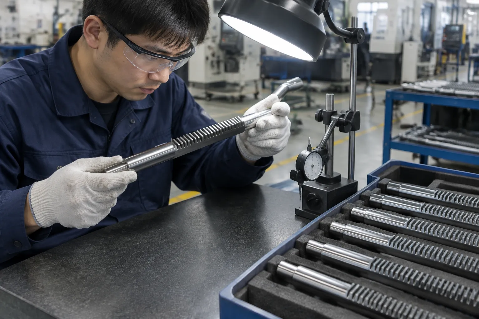
| Surface and tooth inspection | Visual and drawing-defined functional checks |
| Crack inspection | Method and acceptance criterion when required |
| Cycle observation | Measured cycle for this exact configuration |
The commercial guarantee covers only the tested family and acceptance method. A result from one machined round-back rack does not automatically extend to a forged Y-section rack, the same boundary that separates gear shaft straightening from axle shaft straightening.
Automation and Traceability Options
| Level | Suitable situation | Typical scope |
|---|---|---|
| Manual loading | Many variants, lower volume, feasibility stage | Operator loads; machine measures, corrects, verifies |
| Semi-automatic cell | Stable family, operator-supervised handling | Guided loading, automatic cycle, result indication |
| Automatic line | High volume, stable orientation, validated tooling | Conveyor or buffer, gantry or robot, automatic discharge |
| Traceable line | Part-level records required by the quality plan | Part ID, recipe, results, defined line interface |
Common Failure Modes and Controls
| Failure mode | Likely cause | Control |
|---|---|---|
| Jagged, unstable toothed-zone reading | Probe follows teeth instead of centreline | Validated profile-aware measurement, datum correlation |
| Smooth zone OK, tooth-zone function poor | Too few positions, wrong datum | Drawing-defined zones, customer-gauge correlation |
| Tooth or seal-surface mark | Wrong contact location or tool profile | Blocked prohibited zones, dedicated tooling |
| Crack after correction | Excess correction, hardened condition, bad support span | Staged correction, hard limits, required crack inspection |
| Different result after changeover | Tooling or recipe mismatch | Keyed tooling, seating verification, recipe control |
| Machine disagrees with final inspection | Different datum, posture or filtering | Formal measurement-system correlation study |
What Is Not a Universal Promise
Without sample testing and an approved specification, this solution does not promise: one fixed rack diameter, length, tooth length or material range; a fixed final TIR for all variants; correction of every incoming bend; zero tooth marks or zero crack risk without defined inspection; one cycle time, defect rate or labour reduction; proprietary machine learning or automatic improvement by batch; unmanned loading, traceability or MES integration unless ordered and validated; or a named customer result without authorization and records.
Information to Send for a Proposal
Drawing and revision, representative samples, cross-section details, material and hardness, manufacturing route, incoming deformation range, final tolerance, datum, measuring method, approved contact zones, surface and crack requirements, output target and desired automation level. Send them through the contact page for a sample-based feasibility study that defines the measurement model, tooling, correction limits and acceptance evidence for your actual rack family.
Frequently Asked Questions
Can the machine measure directly on rack teeth?
Potentially, but never on a generic round-shaft assumption. The probe, angular sampling and profile model must be validated for that tooth and cross-section, or measurement moves to approved reference zones.
Is press straightening always better than roll straightening?
Press straightening is the common choice for asymmetric, toothed, crack-sensitive components because contact and correction can be localized. Final selection still depends on geometry, contact zones, tolerance and sample results.
Can a hardened steering rack crack during correction?
Any hardened component needs a controlled process window. Material, hardened depth, core condition, incoming bend, support span and correction history all matter, and where the quality plan requires it, crack detection belongs in validation and production inspection.
What accuracy can be guaranteed?
Only the accuracy demonstrated for the agreed workpiece family, datum, gauge and incoming-condition window. Competitor specifications or a value visible in a video are not substitutes for this evidence.
Can the cell connect to an automatic production line?
Yes. Loading, buffers, robots and result communication are engineered after part orientation, cycle and interface requirements are confirmed, as optional project scope rather than default features.
Technical Reference Boundary
- Galdabini steering-rack straightening application
- MAE workpieces and applications
- Public patent on non-round rack measurement and straightening (DE19920003C2)
External figures explain established industry approaches only; they are not represented as specifications, patents or guaranteed performance of machines offered here. Adjacent automotive families, from drive shaft straightening to the wider shaft-type parts portfolio, follow the same evidence discipline.