
Textile-machine shafts guide, rotate or support components that have to run consistently at high production speed. Heat treatment, machining and handling leave these slender parts with bow or radial runout, and an unstable manual correction process only postpones the trouble to grinding, assembly or the final rotation test.
This solution outline is built around shafts approximately 212 mm long, 4.5 to 16 mm in diameter, made from EN31 / SAE 52100 bearing steel at 58-62 HRC. It combines datum-based rotation and measurement with small controlled press corrections and complete remeasurement. The customer’s requested 0.05 mm result, the production-rate assumptions and the final machine configuration all wait for confirmation from drawings and representative sample tests.
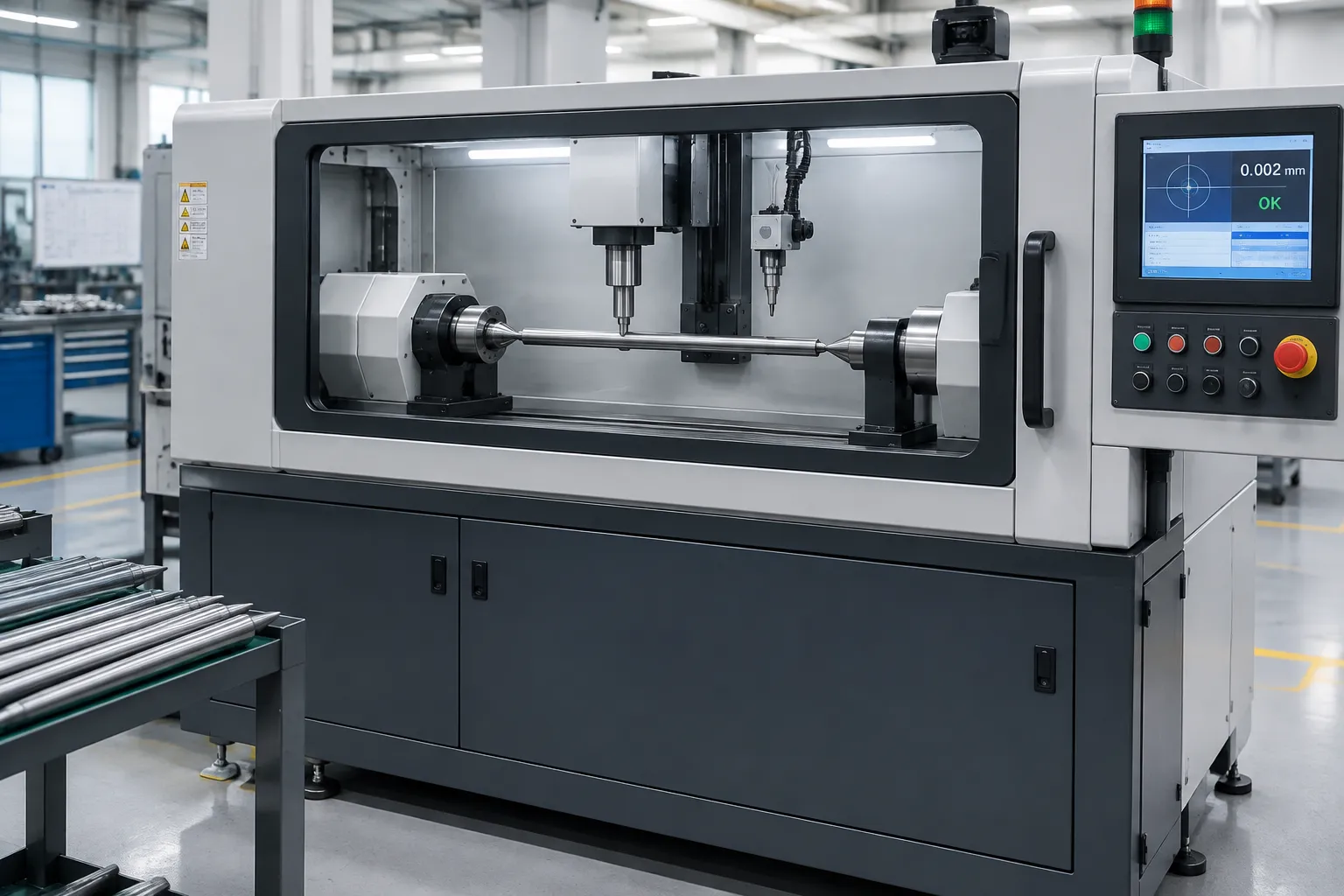
Engineering concept illustration; not proof of an installed line or a guaranteed result.
The Workpiece and the Project Inputs
“Textile shaft” can mean spindle-related shafts, guide shafts, roller shafts and other slender rotating parts in textile machinery. The functional datum may be two journals, centres, a ground outside diameter or another assembly surface, and that datum, not the workpiece name, dictates how the part is supported, rotated and accepted.
The customer reports shafts are corrected today by hammer, at roughly 500 parts per operator per eight-hour shift, against an automated target of 1,000. These are planning inputs, not verified results; they demand a timed trial that includes loading, measurement, correction, remeasurement, unloading, changeover and normal stoppages.
| Project item | Customer input / status |
|---|---|
| Workpiece | Textile-machine shaft; exact function and drawing to be confirmed |
| Diameter range | 4.5-16 mm |
| Approximate length | 212 mm |
| Material | EN31 / SAE 52100 bearing steel |
| Hardness | 58-62 HRC |
| Current method | Manual hammer straightening |
| Requested result | Within 0.05 mm; straightness or TIR and datum to be confirmed |
| Current throughput | Customer input: about 500 parts per operator per 8-hour shift |
| Proposed throughput | Customer target: about 1,000 parts per 8-hour shift; not yet validated |
| Downstream | Grinding problem reported; straightening stage to be confirmed |
| Proposed method | Automatic closed-loop point press-straightening |
Straightness, Runout and the Grinding Datum
Straightness describes deviation from an ideal line. Radial runout or TIR is the variation measured at a specified surface while the shaft rotates about a defined datum. A shaft can pass one definition and fail another the moment the supports, centres or measuring locations change, so the 0.05 mm requirement has to be tied to a drawing characteristic. If the part is ground between centres, the machine may need to reproduce that reference; if the assembly runs on two bearing journals, those journals are the more meaningful datum. Measurement on a rough, interrupted or tapered area creates false signal and stays off the plan without validation.
| Control item | Required definition |
|---|---|
| Controlled characteristic | Straightness, radial runout or TIR |
| Datum | Centres, bearing journals or specified reference diameters |
| Measuring positions | Exact axial locations, acceptable contact surfaces |
| Incoming deformation | Normal distribution and maximum bend before correction |
| Final target | 0.05 mm request; definition and gauge correlation required |
| Surface acceptance | No unacceptable support, measuring or press marks |
| Crack acceptance | No process-induced crack; inspection method to be agreed |
Why Hardened Textile Shafts Are Difficult
EN31 / SAE 52100 is a through-hardening bearing steel chosen for wear resistance and dimensional accuracy. At 58-62 HRC the shaft tolerates neither uncontrolled impact nor excessive local strain, and a correction strategy tuned for a soft blank does not transfer to this condition. The 4.5-16 mm span adds large stiffness differences inside one family: the smallest shaft is sensitive to support error and over-correction, the largest needs a different support span and force range, and section transitions, grooves, threads or ground journals create local response changes and no-press zones. The same envelope-driven thinking applies to any steel shaft and bar family.
| Workpiece-specific challenge | Risk | Required control |
|---|---|---|
| 58-62 HRC hardened bearing steel | Crack initiation or sudden fracture under excess correction | Conservative sample trials, small stroke increments, force and displacement limits |
| Wide diameter range | One recipe under- or over-corrects | Model-specific tooling, support span, correction recipe |
| Slender geometry | Support error and self-deflection distort measurement | Stable datum support, repeatable probe contact |
| Ground or functional journals | Contact marks affect grinding and assembly | Clean contoured supports, approved contact zones |
| Grooves, shoulders, section changes | Stress concentration, misleading readings | Drawing-based no-press and no-measure zones |
| Manual hammer correction | Operator-dependent force and angle | Measured bend direction, closed-loop pressing |
Recommended Method
Automatic point press-straightening is the preferred concept. The system rotates the workpiece on an approved datum, measures bend magnitude and angular position, applies a controlled over-bending stroke at a permitted location, then measures the same points again. That closed loop suits discrete hardened shafts whose correction must be limited and traceable. A continuous roll straightener may suit uniform wire or constant-diameter blanks with continuous bends, but not stepped shafts with protected journals and model-specific press zones. Manual hammer correction stays flexible for very low volume, but it cannot supply recipe control, automatic remeasurement or a process record.
The related project video shows a slender shaft inside a compact measuring and pressing station. It supports the existence of a rotating, press-correcting concept; it does not demonstrate automatic loading, a complete production cycle, final 0.05 mm acceptance, 1,000 parts per shift, or one operator supervising three machines. Those claims require separate project evidence.
| Step | Process | Engineering purpose |
|---|---|---|
| 1 | Part identification and recipe selection | Match diameter, datum, tolerance, supports, correction limits |
| 2 | Loading and datum positioning | Repeatable support without damaging finished areas |
| 3 | Initial rotation and measurement | Map bend magnitude and angular direction at approved points |
| 4 | Signal validation and bend calculation | Separate real deformation from surface or feature variation |
| 5 | Support and press-point positioning | Keep correction load away from grooves and weak transitions |
| 6 | Controlled incremental over-bending | Correct the shaft while limiting strain in hardened steel |
| 7 | Complete remeasurement | Verify response on the same datum and measuring points |
| 8 | Adaptive correction or NOK decision | Repeat only within validated stroke, force and cycle limits |
| 9 | Final sorting and data record | Separate OK/NOK parts, retain process values |
Rotation and initial measurement
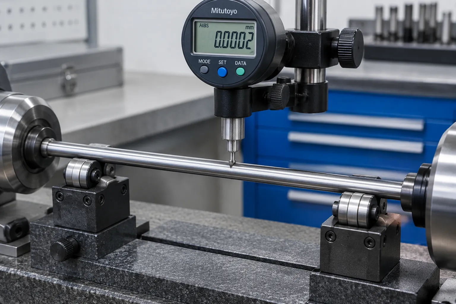
The shaft is supported on the drawing-approved datum and rotated through a controlled cycle while probes record radial deviation at defined axial positions. Probe contact force, filtering and rotation speed stay stable enough that surface texture or a diameter transition is never misread as bend. The controller checks plausibility first: a dirty support, loose part, damaged centre or inconsistent reading raises an alarm or triggers a recheck, not a press command.
Bend calculation and safe correction point
The control identifies the dominant bend direction and an approved axial correction point, staying outside grooves, threads, sharp shoulders, thin sections and finished surfaces. When several measuring points sit out of tolerance, the correction sequence is tested, because one press action can move its neighbours, a coupling familiar from gearbox shaft straightening.
Controlled low-increment pressing
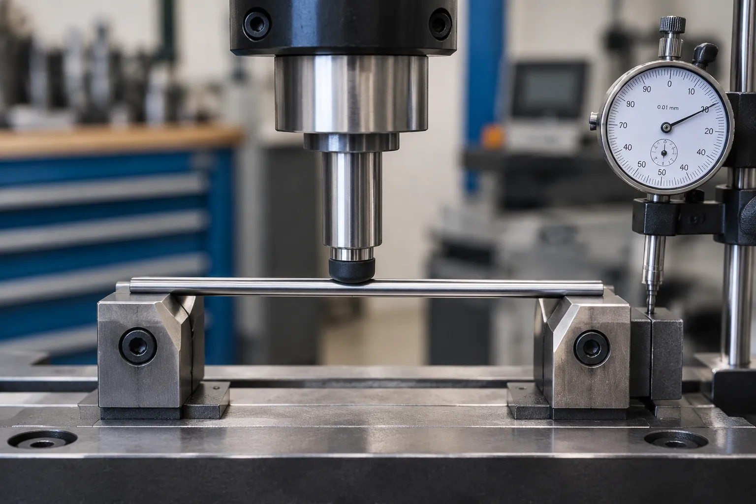
Straightening bends the shaft slightly past the desired final position so elastic springback settles it near straight. For 58-62 HRC bearing steel the first correction increment is conservative and established by sample testing, never assumed. Force and displacement monitoring, where the configuration includes it, adds process limits and abnormal-response detection. The system stops at a validated maximum force, stroke, correction count or abnormal response; a part that does not converge safely is classified NOK or routed to engineering review instead of being pressed again.
Complete remeasurement and sorting
After every correction the shaft is measured again on the same datum, and final acceptance requires all specified points to meet the agreed criterion. Where traceability is required, the record holds part model, incoming and final values, correction count, recipe version and OK/NOK result.
Throughput and Automation Validation
One thousand parts in eight hours averages 28.8 seconds per part if every second of the 28,800 is available. A realistic takt study also covers loading, unloading, multiple press iterations, gauge checks, replenishment, tool cleaning, minor stops and planned availability, so the number stays a target until demonstrated on the agreed shaft mix. The one-operator-three-machines proposal depends on reliable automatic feeding, buffer capacity, low alarm frequency, accessible replenishment and a defined quality-audit plan; 24-hour operation requires staffing, preventive maintenance, tool-life controls and escalation rules, and none of it arrives automatically with the machine.
| Capacity question | Validation required |
|---|---|
| 1,000 parts / 8 hours | Timed run on representative parts including handling and correction loops |
| Mixed 4.5-16 mm family | Changeover time, recipe selection, tooling coverage |
| One operator / three machines | Replenishment workload, alarms, inspection, walking distance |
| 24-hour operation | Staffing, maintenance, consumables, fault recovery, spares |
| Stable 0.05 mm result | Gauge correlation, sample capability, hardness and batch coverage |
Recommended Cell Configuration
| Module | Proposed requirement | Why it is needed |
|---|---|---|
| Machine concept | Automatic point press-straightening cell | Closed-loop correction for discrete hardened shafts |
| Workpiece range | 4.5-16 mm, about 212 mm for this project | Covers the stated family, subject to drawing review |
| Measuring system | Validated contact or non-contact runout measurement | Match approved datum and surface condition |
| Rotation and support | Model-specific centres, rollers or journal supports | Repeatable bend direction, low measurement error |
| Straightening unit | Fine-displacement press with force and stroke limits | Small increments, crack-risk control |
| Tooling | Adjustable, contoured, surface-protective contacts | Avoid marks, protect section transitions |
| Controls | Recipes, plausibility checks, adaptive correction, iteration limits | Manage springback without uncontrolled pressing |
| Loading | Manual, magazine or automated feed per validated takt | Match production requirement honestly |
| Quality data | Before and after readings, correction count, OK/NOK record | Verification and traceability |
| Safety | Guarding, interlocks, overload and abnormal-response protection | Protect operator, tooling, hardened workpiece |
Project Validation Before Final Quotation
Representative samples cover the minimum and maximum diameters, normal and worst-case incoming bends, different heat-treatment batches and every relevant geometry variant. The test records the support and measuring datum, incoming value, each correction, final value, cycle time and any surface or crack observations. The customer’s inspection method and the machine measurement must be correlated before 0.05 mm becomes an acceptance guarantee, and for a hardened shaft with meaningful crack risk the project decides whether visual inspection suffices or an agreed non-destructive method joins validation and production audit.
Information Needed for a Proposal
Send the shaft drawing, exact textile-machine application, material certificate and hardness range, heat-treatment and grinding stage, all diameters and feature locations, incoming bend distribution, target characteristic and datum, approved measuring, support and pressing areas, protected surfaces, target takt, shaft mix, loading direction and representative sample parts. From these the solution team confirms the measuring concept, support span, safe correction zones, force and stroke range, tooling changes, automation level and sample-validation plan. Comparable slender hardened families, such as industrial roller shafts, follow the same input list.
FAQ
Can the machine guarantee 0.05 mm for every 58-62 HRC textile shaft?
Not from hardness, diameter and length alone. The result depends on drawing datum, incoming bend, local geometry, heat-treatment variation, measuring method and permitted correction strain, all validated with representative samples.
Why is hammer straightening hard to control?
Impact force, location and angular direction live in the operator’s hands, and the response is not measured after each strike. A closed-loop machine replaces that with measured bend direction, limited correction and repeated verification.
How is crack risk reduced on hardened bearing steel?
Drawing-approved press zones, conservative incremental strokes, correction limits and complete remeasurement, with force/displacement monitoring and a defined crack-inspection method added per project risk.
Can one machine cover 4.5 to 16 mm shafts?
Potentially, provided supports, measuring range, press resolution, loading hardware and recipe limits cover the stiffness spread. Change tooling should be expected.
Does the video prove 1,000 parts per shift?
No. The video shows the measuring and press station from one angle; throughput requires a timed production trial including handling, correction loops, stops and the actual shaft mix.
What if a shaft does not respond normally?
The machine stops at a validated force, stroke or correction-count limit and classifies the part NOK or engineering review. It never keeps pressing outside a safe process window.
Summary
Hardened textile shafts deserve more than a generic press cycle. The solution reproduces the functional datum, measures the bend reliably, applies small controlled corrections away from sensitive features and remeasures the complete part, all while managing the crack risk of 58-62 HRC bearing steel. Send textile shaft drawings, incoming bend data, the 0.05 mm acceptance definition, production mix and sample information for a feasibility review; the final machine and automation proposal should stand on a timed trial, not on a shift-target estimate.