
Automotive axle shafts carry torque from the differential to the wheels while absorbing cyclic bending and torsion. Forging, heat treatment and machining all leave residual deformation along the shaft body, bearing journal, spline or flange reference, and when those features stop running within drawing requirements the damage spreads outward: machining allowance, seal and bearing life, spline engagement, flange alignment, vehicle vibration.
This solution outline reflects a real customer enquiry for flanged axle shafts 1000-1350 mm long, with drawing limits stated separately for bearing-journal runout, shaft-body runout, spline runout and flange-hole pitch-circle runout. Those figures are customer requirements, not confirmed production results; final machine selection and any guarantee depend on drawing review, gauge correlation and representative sample tests.
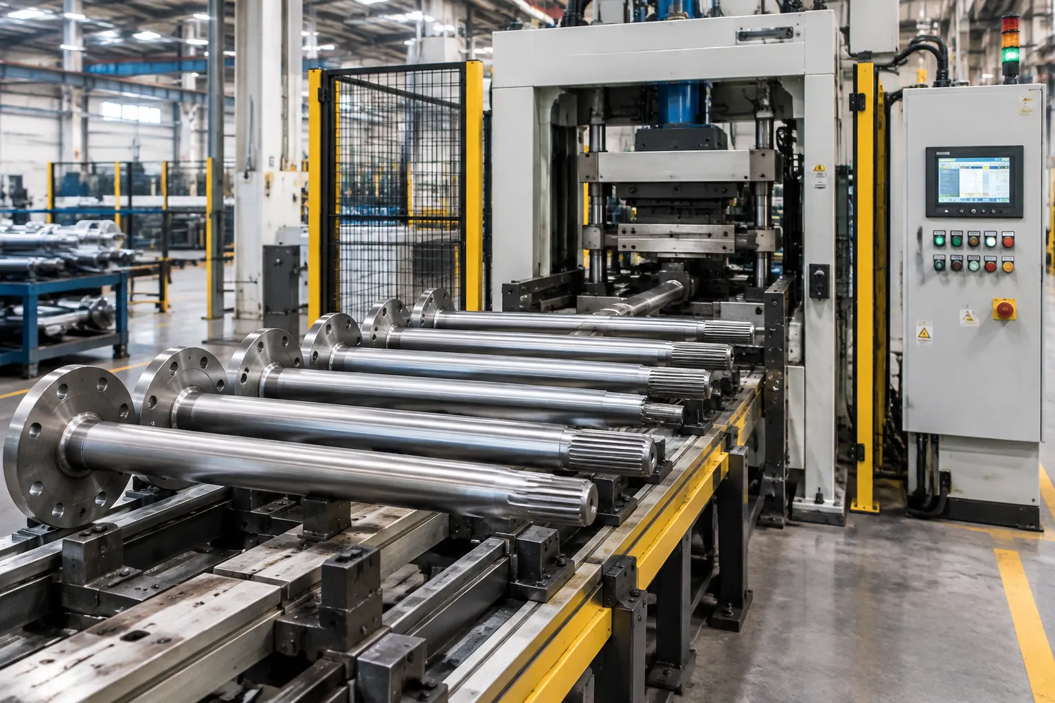
Engineering concept illustration; the layout shown is not proof of an installed customer line or a guaranteed result.
Geometry and Project Requirements
Unlike a constant-diameter bar, this axle shaft stacks a large flange, a long shaft body, a bearing journal and a splined end on one part, and each feature can demand a different datum and inspection tool. The flange alone complicates automatic rotation, loading and balance compared with a symmetrical smooth shaft.
The customer currently runs a premium European straightening system and is evaluating an alternative. A credible comparison is never the general claim that two machines perform identically; it uses the same axle family, measuring datum, incoming deformation, target tolerances, cycle time, surface criteria, traceability requirements and one agreed acceptance study.
| Project item | Customer requirement |
|---|---|
| Workpiece | Flanged automotive axle shaft / half shaft |
| Overall length | 1000-1350 mm |
| Flange diameter | 212.0 mm |
| Bearing journal diameter | 57.15 mm |
| Shaft body diameter | 57.15 mm |
| Spline outside diameter | 59.43 / 59.69 mm |
| Spline length options | 54.0 / 135.0 / 215 mm |
| Journal runout | 0.10 mm max |
| Shaft body runout | 0.50 mm max |
| Spline runout | 0.050 mm max |
| PCD flange-hole runout | 0.050 mm max |
| Material / hardness | To be confirmed from drawing and heat-treatment specification |
| Target cycle / volume | To be confirmed |
One Axle Shaft, Four Different Measurement Problems
The shaft body and bearing journal lend themselves to contact or non-contact displacement sensing while the part rotates on an agreed datum. The spline is different: probe contact across teeth produces a waveform shaped by tooth geometry, not only by the true centreline. The flange-hole pitch circle is different again, often needing angular indexing, vision, a master fixture or another dedicated method. So “the machine measures runout” is not a specification. The distinction between shaft straightness, radial runout and TIR has to live inside the inspection plan, and the proposal must state what is measured, how, against which datums, and whether every tolerance is checked inside the straightener or by a downstream gauge.
| Characteristic | Possible datum / method | Main risk |
|---|---|---|
| Bearing journal runout | Rotate on specified journals or centres; displacement sensor | Support error, surface contamination |
| Shaft body runout | Multi-point measurement along the body | Self-weight, long support span |
| Spline runout | Master spline or gear, optical method, validated smooth reference | Tooth-form signal mistaken for centreline error |
| PCD flange-hole runout | Indexed hole measurement, vision, dedicated gauge | Wrong angular reference, flange seating error |
The exact method follows the drawing and the customer’s existing inspection standard, because a machine result only means something when it correlates with the customer’s final gauge.
Why Flanged Axle Shafts Are Hard to Straighten
The 1000-1350 mm length with a large flange produces asymmetric mass distribution. Loading equipment has to carry the part without letting the flange strike sensors, rails or guards, and during rotation the system controls axial position and angular orientation while keeping the long shaft stable. Several stiffness transitions wait inside the geometry: pressing near a flange transition, spline end or undercut concentrates stress, and pressing on a bearing or sealing journal leaves an unacceptable mark. Because spline and flange-hole tolerances are ten times tighter than the shaft-body requirement, correcting one section without the complete datum chain can push another feature out of specification.
| Challenge | Consequence | Required control |
|---|---|---|
| Long, flange-heavy geometry | Unstable loading or measurement | Dedicated supports, flange clearance, balanced rotation |
| Several tolerance zones | One OK reading proves nothing about the rest | Multi-feature inspection, separate acceptance limits |
| Spline tooth geometry | Noisy or misleading runout signal | Master, optical or specially filtered measurement |
| Flange-hole PCD | Needs angular reference, not surface probing | Indexed or vision-based verification |
| Heat-treated material | Variable springback, crack risk | Material data, conservative strokes, sample validation |
| Finished journals and splines | Marks or functional damage | Protected zones, contoured contact tooling |
Recommended Straightening Concept
For this family, an automatic point press-straightening system with controlled rotation, multiple axial measuring positions and model-specific tooling is the right starting concept. A continuous roll straightener fits a plain bar or tube; a finished shaft with a 212 mm flange, a spline and several functional diameters cannot pass through uniform rolls the same way, and should not be asked to. Related long-shaft automation follows the same logic across the family, from drive shaft straightening to industrial transmission parts.
The reference project video shows loading rails presenting multiple long flanged shafts to a press-straightening station. It evidences the material-flow and pressing concept, not the listed tolerance capability, measuring technology or cycle time, which stay inside project validation.
The Automatic Process, Step by Step
1. Part identification and safe loading
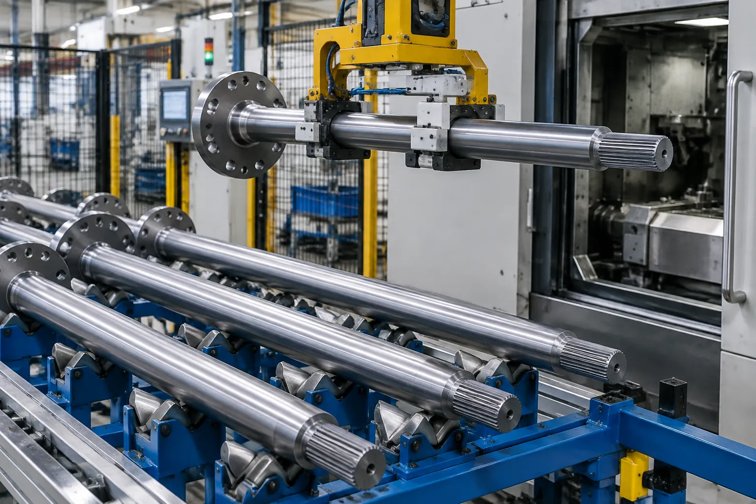
Engineering concept illustration; rail geometry, transfer sequence and protection zones require the approved drawing and trials.
The loader singulates one axle shaft and transfers it in with the flange orientation controlled. Rails and lifting elements clear the 212 mm flange and the different spline lengths, and where several models share the line, barcode, DMC or mechanical poka-yoke keeps the wrong recipe or tooling out of reach.
2. Datum location and rotation
The part is located on approved journals, centres or dedicated supports per the inspection datum. The system controls axial movement and rotates the axle through a complete measuring cycle, with flange eccentricity and unbalanced mass respected in rotation speed and support pressure.
3. Initial multi-point measurement
Sensors record journal and shaft-body runout at defined axial positions; if spline or flange-hole PCD inspection belongs in the line, the master, optical or indexed unit runs under its own acceptance method. The controller rejects implausible readings from dirt, unstable contact or a missed angular reference and refuses to compute a correction until datum and waveform are consistent.
4. Correction strategy calculation
The system resolves the dominant bend position and angle, then picks approved support and pressing locations from the model recipe. A shaft with several bend peaks may need more than one correction point, sequenced to minimize strokes and to avoid pushing deformation toward the flange, spline or a finished journal.
5. Controlled press straightening
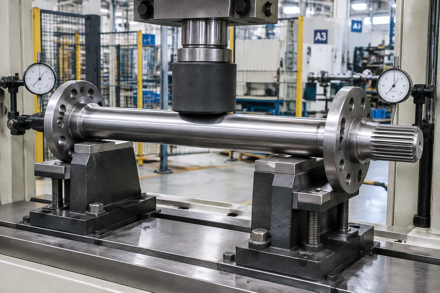
Engineering concept illustration of one controlled correction stroke; final press position and process limits remain validation items.
The axle indexes until the bend direction sits under the press, and a controlled over-bending stroke lands at a safe shaft-body location to compensate elastic springback. Initial stroke, maximum stroke and the permitted correction count come from representative sample tests. Press tool and supports distribute contact without marking protected surfaces, and force monitoring, where fitted, catches abnormal parts, wrong models, tooling errors or unexpected material response, with limits set from project evidence rather than defaults.
6. Closed-loop remeasurement
Each correction is followed by the same datum and measuring sequence. The controller compares every required feature against its own tolerance instead of trusting one overall value, and additional correction is allowed only when the response stays plausible and within validated limits.
7. Final inspection and sorting
An OK result requires every in-line controlled characteristic to pass. If the line does not measure spline or flange-hole PCD runout directly, the quotation says so plainly and assigns those checks to a downstream station or the customer gauge. Parts that exhaust a correction, force, stroke or consistency limit sort to NOK or manual review, and the system can record incoming and final readings, correction positions, stroke counts, recipe and part ID for traceability.
Proposed Cell Configuration
| Module | Proposed configuration |
|---|---|
| Machine concept | Automatic point press-straightening line for long flanged axle shafts |
| Workpiece handling | Flange-compatible loading rails, lift and transfer, controlled unloading |
| Datum / rotation | Centres, journal rollers or dedicated locating per drawing |
| Shaft measurement | Multi-point contact or laser displacement |
| Spline measurement | Master spline or gear, optical or validated alternative if in-line |
| Flange PCD measurement | Indexed probe, vision or separate gauge if required |
| Press tooling | Adjustable supports, contoured press contact on approved areas |
| Controls | Model recipes, correction calculation, springback adaptation, OK/NOK limits |
| Traceability | DMC or barcode, before/after values, correction history |
| Safety | Interlocked guarding, overload protection, flange-clearance monitoring |
Validation and Competitor-Replacement Acceptance
Replacing an incumbent premium machine starts from an agreed acceptance matrix, not a price argument. The matrix lists each axle model, material condition, incoming deformation, measuring datum, required tolerance, maximum cycle time, surface criteria, tooling change time, traceability and maintenance requirement. Representative samples span minimum and maximum length, both spline diameters, all spline lengths and normal plus worst-case incoming bends. The test report compares the customer’s gauge with the proposed machine on the same parts and documents repeatability over a meaningful sample set; only those validated results belong in any public manufacturing case.
Information Needed for a Proposal
Complete drawings, material and heat treatment, part weight, all shaft and flange dimensions, journal, spline and flange-hole datums, incoming runout distribution, target tolerances, protected surfaces, allowed pressing zones, target takt time, annual volume, loading orientation, traceability requirements and representative samples. These details decide the measuring units, support positions, press capacity, handling layout, and whether spline and flange-hole PCD inspection belongs inside the straightener or in a separate gauge station. The same input discipline applies to every automotive shaft project, including industrial roller shafts and the families collected under the shaft-type parts overview.
FAQ
Can one machine control journal, shaft body, spline and flange-hole runout?
Potentially, but these features may need different measuring technologies, and the final line must state which checks run in-line and which belong to a separate gauge.
Why is spline runout harder to measure?
A probe touching individual teeth picks up tooth-form variation along with centreline error, so a master spline or gear, an optical system or another validated method is usually required.
How are the spline and flange protected during pressing?
The model recipe defines approved support and press locations on safe shaft sections. Splines, finished journals, flange faces and holes are protected zones unless a dedicated contact method has been validated.
Can the machine handle 1000-1350 mm axle shafts automatically?
The video confirms a long-shaft loading and press concept, but final length, weight, flange clearance, support travel and cycle time are checked against the actual drawing and machine configuration.
Can this solution replace an existing premium system?
That is decided by a like-for-like acceptance test covering accuracy, cycle time, tooling, traceability, maintenance and service, never by an unsupported general equivalence claim.
What is required before quotation?
Drawing, material and heat treatment, part weight, incoming and target runout, datum and measuring method, allowed press areas, production volume, takt time and sample parts.
Summary
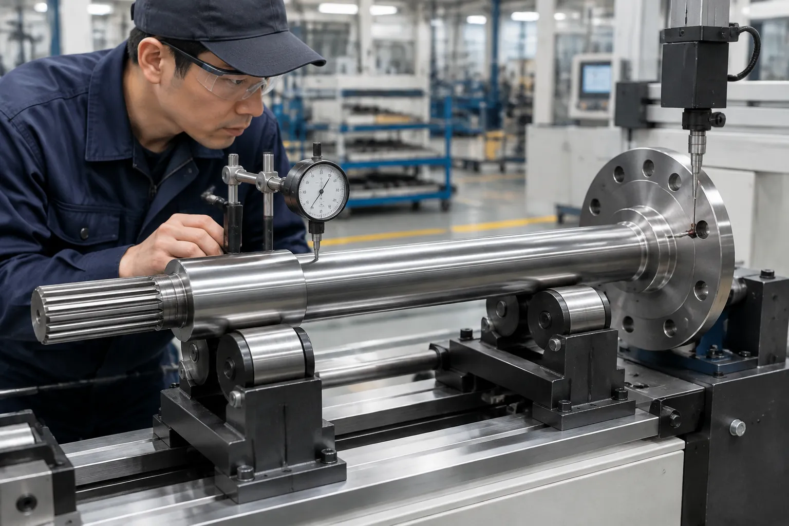
An automotive axle shaft is not a simple long bar. Journal, shaft body, spline and flange-hole pitch circle form four separate measurement and acceptance problems, while the large flange reshapes loading, rotation and support design. A reliable solution combines controlled material handling, datum-based multi-feature measurement, protected point pressing and closed-loop verification. Send the axle drawings, incoming runout data, target tolerances, production requirements and samples for a feasibility and competitor-replacement study; the final proposal should stand on an agreed measurement and acceptance matrix, not on equipment price or nominal dimensions.