
A drive shaft can look like a simple long tube, but its straightening problem is defined by the complete torque-transmission geometry. The tube body, welded ends, yokes, flanges, universal-joint interfaces and any centre-bearing features all have to stay aligned, without crushing the hollow section and without confusing geometric runout with dynamic unbalance.
A reliable drive shaft straightening solution therefore starts from the part drawing, the assembly stage and the acceptance method. It defines the functional reference axis, the angular orientation, the measuring stations, the protected areas, the permitted correction zones and the relationship between straightening and the downstream balancing process.
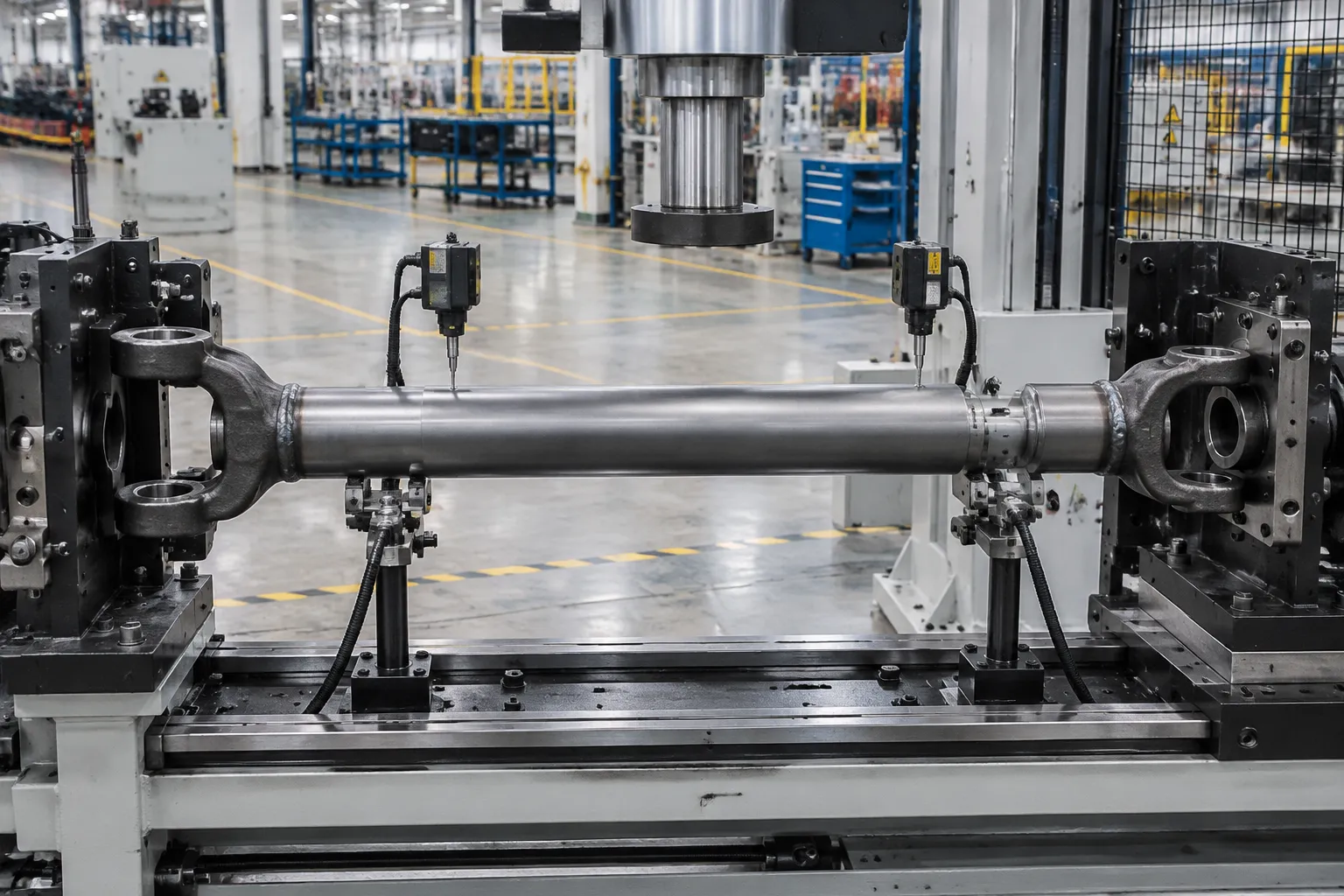
Engineering concept illustration, not a customer-site photograph. Machine span, guarding, tooling, sensors and correction capacity depend on the drive shaft family and sample tests.
Why Drive Shafts Need a Dedicated Solution
| Drive shaft feature | Straightening risk | Project response |
|---|---|---|
| Hollow welded tube | Local loading dents, ovalizes or collapses the section | Tube-specific conforming supports and correction tooling |
| End yokes, flanges, couplings | Ordinary chucks seat inconsistently or damage interfaces | Locate from approved features with repeatable angular positioning |
| One-piece or multi-piece build | Each section has its own reference and support condition | Freeze the exact assembly configuration and measuring route |
| Welded joints | Weld distortion shifts tube axis and end relationship | Measure at drawing-based stations before and after welding stages |
| Universal-joint interfaces | Joint clearance and articulation obscure the true reference | Define whether joints are installed, locked, substituted by masters or excluded |
| Long span | Self-weight and support placement change the measured curve | Validate support coordinates and correlate with the customer gauge |
| High-speed operation | Runout and mass unbalance both cause vibration | Treat geometric straightening and dynamic balancing as separate controls |
| Angular phase requirement | Correct runout does not guarantee correct yoke-to-yoke phase | Measure or mechanically preserve phase as an independent characteristic |
The objective is never just a smaller indicator movement at one convenient tube location. It is the specified geometry held while the tube, welded zones, joint interfaces and downstream balance condition all survive the process.
Define Which “Drive Shaft” Is in Scope
Drive shaft, propeller shaft, cardan shaft and transmission shaft get used interchangeably, so a proposal should replace the generic name with an exact part family:
| Part family | Typical construction | Main straightening question |
|---|---|---|
| One-piece automotive propeller shaft | Hollow tube with welded yokes or flanges | Tube runout, end alignment, phase and balance sequence |
| Multi-piece propeller shaft | Two or more tubular sections with centre-bearing features | Section references, centre-bearing datum, assembled behaviour |
| Industrial cardan shaft | Tubular or solid body with articulated couplings | Coupling location, telescopic section, operating-angle requirements |
| Bare drive-shaft tube | Tube before final end assembly | Tube straightness, ovality, weld-preparation allowance |
| Assembled drive shaft | Tube, yokes, joints, flanges, balance weights | Complete-assembly runout, phase, final balance validation |
The drawing and sample decide whether the target is a bare tube, a welded shaft, a jointed assembly or a finished balanced component. A process validated at one stage does not transfer automatically to another, a rule that holds across the whole shaft portfolio from motor shafts to transmission parts.
Keep Drive Shaft, Axle Shaft and Steering Shaft Separate
These components all transmit motion or torque, but their geometry and acceptance logic are not interchangeable:
| Component | Common geometry | Content focus |
|---|---|---|
| Drive / propeller shaft | Long hollow tube with welded yokes, flanges or couplings | Tube protection, end alignment, phase, runout-balance boundary |
| Axle / half shaft | Usually solid or locally hollow stepped shaft with spline and wheel flange | Journal, spline, shaft-body and flange relationships |
| Steering shaft | Smaller column member, often telescopic or jointed | Interface geometry, collapsible features, safety requirements |
The automotive and steering navigation layers collect these families; this page answers the drive-shaft-specific manufacturing and equipment questions without flattening every automotive shaft into one workpiece.
Freeze the Manufacturing and Repair Stage
Bare tube before end welding
Access is simple, but later welding introduces new distortion. Straightening here can serve incoming tube control or preparation; it never replaces post-weld measurement.
Welded shaft before final machining
Yokes, flanges or stubs are already attached, so the machine can evaluate their relationship to the tube. Remaining machining allowance and heat input join the plan.
Finished shaft before balancing
This stage fixes the geometric condition that enters the balancing machine. Surface protection, joint handling and correction limits tighten because more value rides on every part.
Previously balanced shaft
With balance weights present, pressing can change tube geometry, weight position or the measured balance condition. The part returns to the approved balancing check after straightening unless the customer process explicitly demonstrates otherwise.
Rebuild or repair shaft
Wear, denting, damaged joints, bad welds and previous correction attempts may rule straightening out. The inspection plan includes rejection rules, because an automatic straightener is not a structural repair assessment.
Define the Controlled Characteristic
“Straight shaft” is not an acceptance requirement. The drawing may separately control tube or shaft-axis straightness; circular or total runout at specified stations; runout of end pilots, journals, flange faces or coupling features; concentricity of end features; yoke or flange angular phase; tube outside diameter and ovality; weld-related geometry with permitted correction zones; residual unbalance of the rotating assembly; and functional vibration or noise in a final system test.
Straightening influences geometric runout. It does not automatically correct phase error, joint wear, flange-face error, weld quality or mass unbalance, and pretending otherwise is how projects fail acceptance.
Build the Measurement from the Functional Reference
The reference axis must match the drawing or carry documented correlation to the customer gauge. End pilots or flange registers can reproduce the installed rotational axis when their form and condition qualify; dedicated masters or chucks can locate from the joint interface once clearances, bearing-cup condition and articulation are controlled; on multi-piece shafts the centre-bearing journal may be a datum, an inspected feature or just a temporary support, and the plan has to say which; and sensors can compute a mathematical axis from several measured features, provided the algorithm, station coordinates, filtering and outlier rules are validated against the approved gauge.
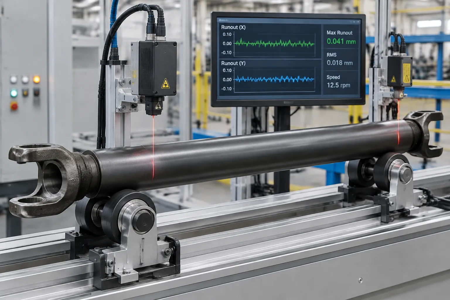
Concept illustration of non-contact tube measurement and end-feature orientation; it does not prescribe a specific sensor technology for every project.
Do Not Read an Irregular Tube Surface as the True Axis
A welded or formed tube carries local surface variation, seam effects, coating, weld spatter and ovality, so one circumferential track mixes centreline motion with surface-form error:
| Measurement variable | Possible false signal | Control method |
|---|---|---|
| Tube surface texture | Short-period displacement variation | Approved track selection, validated filtering |
| Ovality | Two-lobe signal resembling runout | Separate diameter/form measurement or multi-direction sensing |
| Weld seam | Local peak or reflectivity change | Defined seam handling, sensor suitability check |
| Coating or contamination | Unstable contact or optical response | Cleanliness and surface-condition rules |
| Joint clearance | End feature moves without tube bend | Lock, preload, master or exclude the joint as validated |
| Fixture seating | Re-clamping changes the indicated high point | Repeat-load and re-seat studies |
| Long-span sag | Support-dependent apparent curvature | Freeze support positions and orientation |
The system maps several axial stations instead of inferring the whole shaft from one midpoint reading, and it preserves station data for process review when traceability is required.
Preserve Yoke and Flange Phase
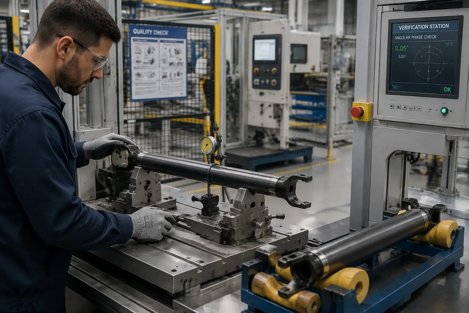
Phasing is the angular relationship between end features, yokes above all. It is not straightness, and it is not corrected by reducing tube runout. The project defines: the feature that establishes zero angle; the permitted phase relationship and tolerance; how each end is located without joint play; whether the machine only preserves phase or also verifies it; whether pressing is allowed at every angular orientation; how a failed phase check is handled; and whether phase is checked before straightening, after, or both. An angular locator, vision system or feature-specific probe may do the work, but selection follows the actual yoke, flange or coupling geometry, and the machine must never rotate a fragile feature, weld or balance weight into an unsafe load path.
Protect the Hollow Tube from Collapse and Indentation
Tube protection is the defining tooling problem of propeller shaft work. Narrow supports or a small press nose can deliver a locally acceptable runout number while permanently damaging the cross-section.
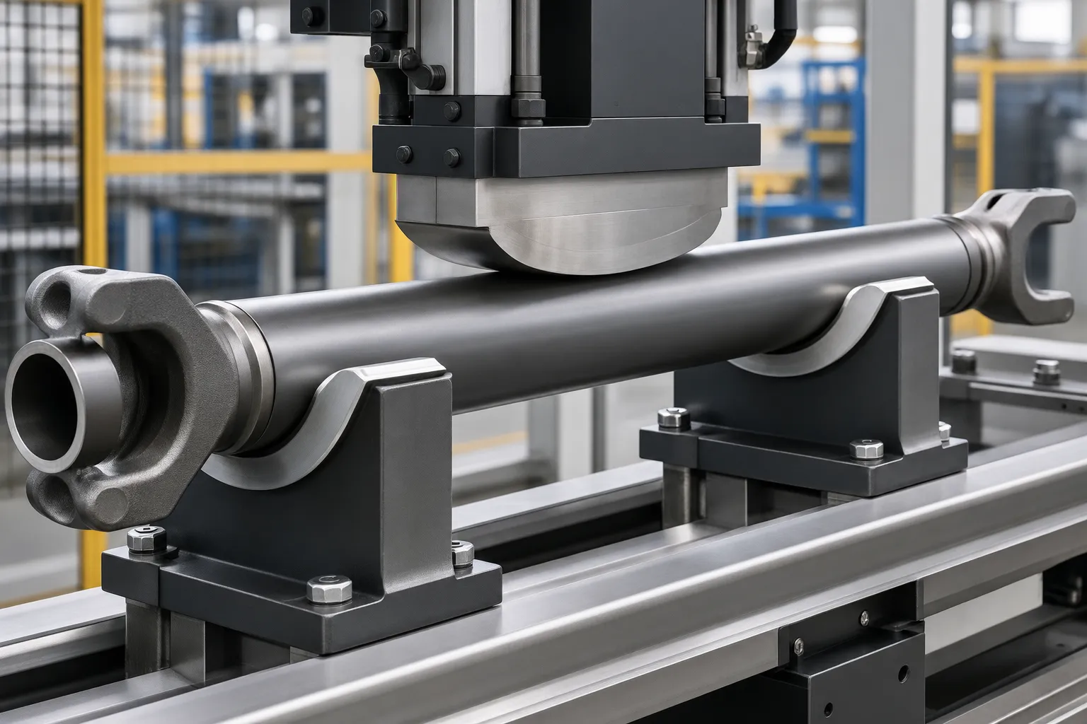
Concept illustration of broad conforming contact; actual saddle radius, liner, contact length and force limit require sample validation.
Conforming supports
Broad saddles spread reaction force over a larger arc. Diameter match, liner material, edge radius and cleanliness are chosen for the tube surface and the load.
Enveloping correction tooling
A radiused or enveloping press shoe cuts local contact stress compared with a narrow punch while still delivering the controlled bending moment at the selected span.
Internal support when required
Some tube families need a mandrel or plug. Internal tooling adds access, changeover and marking risks, so it appears only when the sample study proves the need.
Ovality and surface checks
Post-correction acceptance includes the specified tube diameter, ovality, dent and surface criteria. A shaft is not acceptable merely because its radial indicator value improved.
Map Welds, Balance Weights and No-Press Zones
Drawing and sample review identifies every region that cannot be loaded or contacted: circumferential or longitudinal welds; heat-affected zones with project-specific restrictions; balance weights and their attachment zones; thin transitions near yokes and flanges; grease fittings, seals and joint hardware; splines, threads, pilots and finished bearing surfaces; labels, coatings and corrosion-protection areas; and dents, cracks or prior repair zones that demand rejection. The recipe converts these into axial and angular keep-out zones. When the safe correction window gets too small, the right decision may be a different manufacturing sequence or a rejected part, not a forced unsafe correction.
The Closed-Loop Process, Nine Steps
- Identify the part and stage. Recipe selected from part number, barcode or data matrix; bare tube, welded shaft, assembled shaft or repair confirmed.
- Inspect and load safely. Visible dents, damaged joints, loose weights, severe weld defects and other reject conditions checked; the shaft loaded without striking yokes, flanges or tube.
- Locate functional datums and the angular feature. Approved end interfaces seated, phase reference established, incomplete seating detected before rotation.
- Measure multiple axial stations. Controlled rotation builds the bend and runout map; known surface-form effects separated from centreline motion by the validated method.
- Select a safe correction zone. The control combines the deviation map with tube stiffness, support span, weld locations, end geometry, phase orientation and all no-press zones.
- Apply controlled over-bending. Broad supports and conforming tooling moved to approved coordinates; limited stroke or force per the validated model. Loaded displacement is never the final geometry.
- Release and remeasure. Load removed before judgement; relevant stations re-measured; springback model updated from released results.
- Verify independent characteristics. Required runout stations, phase, end-feature geometry, tube ovality, surface condition and specified weld-zone checks; the shaft routed to balancing or assembly per the control plan.
- Record and unload. Part identity, recipe revision, before and after values, correction history, alarms and disposition stored; the shaft unloaded without shifting joint position or damaging finishes.
Straightening and Dynamic Balancing Are Different Processes
Geometric runout describes how a realized surface or feature moves relative to a reference during rotation. Dynamic unbalance describes mass distribution and the forces generated when the assembly spins. A drive shaft can be geometrically straight yet unbalanced, or carry low residual unbalance while still showing unacceptable runout:
| Process | Primary input | Typical correction | What it does not prove |
|---|---|---|---|
| Straightening | Bend/runout map, approved geometric datums | Controlled bending at safe locations | Residual unbalance within tolerance |
| Phase verification | Angular relationship of end features | Assembly or indexing correction, rejection | Tube centreline and mass distribution acceptable |
| Dynamic balancing | Rotating unbalance magnitude and angle per plane | Add, remove or relocate mass | Shaft geometry, weld integrity or phase acceptable |
For most completed shafts the defensible route is correcting excessive runout before final balancing, then verifying balance after any later geometric correction, with the exact sequence following the customer drawing, balance specification and validated manufacturing route. Straightening is not a substitute for a balancing machine.
Point Press or Roller?
A completed propeller shaft contains discrete yokes, flanges, welds and protected zones, which favours controlled point-press correction with dedicated supports because the machine targets selected axial and angular locations. Roller straightening suits suitable bare constant-section tube or bar stock, not finished jointed shafts. The same cross-section fragility that shapes hollow shaft straightening rules out roll contact on a finished tube with machined ends.
Proposed Cell Configuration
| Cell function | Project-specific configuration |
|---|---|
| Part handling | Manual, assisted or automated loading per mass, length, volume |
| End location | Dedicated flange, pilot, yoke or coupling tooling with seating detection |
| Angular positioning | Mechanical locator, encoder, vision or feature sensor as validated |
| Rotation | Controlled low-speed indexing with joint and fixture security checks |
| Measurement | Contact or non-contact sensors at drawing-based stations |
| Support | Adjustable broad saddles matched to tube diameter and load |
| Correction | Servo-electric or hydraulic press with force/displacement monitoring |
| Recipe control | Part-family parameters, protected zones, revision management |
| Quality checks | Runout, phase, tube form, surface, end-feature checks |
| Traceability | Before/after data, correction history, alarms, disposition |
| Safety | Guarding, interlocks, risk assessment for rotation and stored energy |
Machine capacity is not selected from overall length alone. Tube diameter and wall thickness, material, yield behaviour, support span, end mass, incoming deformation and safe contact area all shape the required force, stroke and tooling, exactly as in gearbox shaft straightening projects.
Sample Testing and Acceptance
Before final machine and tooling commitments, a representative sample study covers: minimum and maximum tube diameter, wall thickness and length; one-piece and multi-piece variants if both are in scope; all relevant yoke, flange and coupling interfaces; actual material, heat treatment, weld condition and coating; realistic incoming runout magnitudes and bend locations; parts carrying approved balance weights; normal and difficult phase orientations; and customer-approved measurement and balance correlation samples.
The acceptance plan then defines the incoming distribution, target characteristics, gauge agreement, repeat-load repeatability, surface and ovality limits, permitted correction count, crack or weld inspection requirements, cycle-time boundary, traceability and the disposition of nonconforming parts.
Information Needed for a Proposal
- 2D drawing and, when available, 3D model;
- part names and one-piece / multi-piece construction;
- overall length, tube outside diameter, wall thickness;
- material, heat treatment, coating, weld information;
- yoke, flange, coupling and centre-bearing details;
- assembly stage at which straightening occurs;
- drawing datums and every controlled runout or straightness station;
- phase requirement and reference features;
- incoming deformation distribution, not only the worst sample;
- allowed support and correction zones;
- protected surfaces, welds, weights and no-press zones;
- ovality, dent, surface and crack acceptance rules;
- balancing stage, specification and required process sequence;
- model mix, batch size, target throughput, loading method;
- traceability, data export and line-integration requirements;
- representative good, typical and difficult samples;
- customer gauge or gauge-correlation method.
FAQ
Can a drive shaft straightener also balance the shaft?
Not automatically. Straightening controls specified geometry; balancing measures and corrects mass distribution during rotation. A cell may connect both operations, but each needs its own measurement system, correction method and acceptance criteria.
Why correct runout before final balancing?
Excessive geometric runout interferes with repeatable support and rotating behaviour, so correcting it first gives balancing a more stable input. The approved order must still be validated for the exact shaft, tooling and balance specification.
Can the machine straighten a shaft with universal joints installed?
Possibly, with dedicated tooling and a controlled joint condition. Joint clearance and articulation create false measurements, so the project defines how joints are located, locked or represented by masters.
How is a hollow tube kept from being crushed?
Tube-specific support and correction concepts: broad conforming saddles, radiused or enveloping press shoes, force and stroke limits, and internal support when justified. The design is proven on representative samples and checked for ovality and surface damage.
Does acceptable tube runout prove correct yoke phase?
No. Runout and phase are independent characteristics; the phase reference and tolerance are measured or mechanically preserved separately.
Can one machine handle different lengths and diameters?
Yes, when the families fall inside the validated force, span, rotation, sensor and tooling envelope. Adjustable stations and stored recipes support changeover; end interfaces and tube diameters may need dedicated tooling.
Can a previously balanced drive shaft be straightened?
Potentially, but correction can affect the balance condition or weights. The part returns to the approved balancing verification afterwards unless the customer process explicitly establishes another route.
Common Failure Modes
- Tube dimpled under the saddle. Support or press tooling narrower than the validated arc leaves a flat that passes runout today and cracks in service. Contact width is a process parameter, not a detail.
- Runout fixed, phase broken. The correction lands without regard to yoke orientation and the shaft leaves the cell straight but out of phase, which no balancing machine will forgive.
- Balanced shaft pressed without rebalancing. Geometry improved, balance shifted, vibration returned. Every corrected balanced assembly goes back through the balance gate.
- Joint clearance read as bend. A worn or unlocked universal joint lets the end feature wander during rotation; the controller corrects a bend that lives in the fixture, not the part.
- Weld zone loaded without documentation. Pressing across a circumferential weld without weld-procedure knowledge risks a defect that runout inspection will never see.
Build the Solution from the Complete Rotating Assembly
A drive shaft straightening solution protects far more than the tube centreline. It coordinates the functional axis, tube form, welded ends, yoke or flange phase, protected features and the downstream balancing route. Splined shafts add their own datum questions, covered by the spline shaft straightening machine page; the wider machine family is described in the shaft-type parts overview. Share the drive shaft drawing, sample condition and process targets, and the engineering response should be a sample-test plan and a project-specific proposal rather than a catalogue page.