
A pump shaft does more than transmit torque. It positions bearings, carries the impeller or displacement element, passes through a seal system and connects the whole rotating assembly to the driver. Even a small bend therefore surfaces in several places at once: bearing-journal runout, seal-surface motion, coupling error, lost impeller clearance, rotor vibration.
Five questions decide any pump shaft straightening solution long before machine selection:
- Is the workpiece a bare production shaft, a repair shaft or an assembled pump rotor?
- Which bearing, centre or functional journal defines the rotation axis?
- Is the measured signal a true bend, local form error, setup error, self-weight sag or assembly error?
- Which lands may be supported and pressed without damaging seal, bearing or fit surfaces?
- How will released geometry and the downstream rotor assembly be verified?
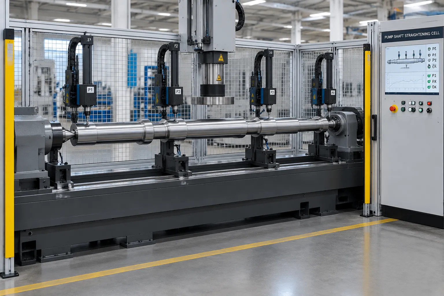
Engineering concept illustration of a bare stepped pump shaft in a closed-loop straightening cell. Not a customer-site photograph and not performance evidence; support locations, sensor tracks and force limits come from the drawing and sample tests.
Pump Shaft Straightening Is Not One Application
Search results for “pump shaft straightening machine” mix automatic production equipment with service-centre repair methods. Related problems, but not interchangeable offers:
| Pump-shaft family | Typical context | Straightening decision |
|---|---|---|
| Centrifugal-pump bare shaft | New production after turning, heat treatment, grinding | Closed-loop runout measurement and controlled correction may suit |
| Multistage pump shaft | Long stepped shaft carrying impellers and sleeves | Multi-track datum map, self-weight control, protected contact study |
| Vertical turbine lineshaft | Very long slender shaft assembled in sections | Segment identity, support spacing, thread and coupling protection critical |
| Close-coupled pump rotor | Shaft integrated with motor rotor or pump cartridge | Separate assembled-rotor study; never treat as a bare shaft |
| Hydraulic pump shaft | Compact shaft with splines, gears, swash-plate interfaces | Short-span, feature-rich measurement, restricted press map |
| Repair or remanufacturing shaft | Unknown heat, corrosion, wear or repair history | Inspect and classify before choosing mechanical, heat or peening repair |
| Reciprocating PD pump shaft | Crankshaft or camshaft geometry | Use the dedicated crankshaft or camshaft process, not this page |
This page concentrates on bare, one-piece industrial pump shafts. Complete rotors, welded assemblies, built-up shafts and field alignment problems take separate engineering routes, and extreme-service variants such as ESP pump shafts or mud motor rotors have their own pages.
Freeze the Pump and the Process Stage
The same drawing can demand different treatment at different stages.
After rough turning
Machining stock still sits on bearing and seal journals, so controlled correction can protect downstream grinding allowance, provided the datum strategy matches the intended finished axis.
After heat treatment
Distortion may be correctable, but hardness, case depth, residual stress and crack risk become process inputs. A recipe tuned on an annealed shaft transfers to a hardened one only after trials.
Before final grinding
Straightening and grinding stock have to be planned together. Grinding fixes local diameter and form; it should not quietly absorb a bent common axis.
After final grinding or coating
Bearing seats, seal running surfaces, threads, splines and coatings are finished. Contact protection and surface inspection tighten, and some shafts belong in the reject chute or another process rather than under a ram.
Repair or service return
Wear, corrosion, fretting, thermal damage, seizure, crack indications and prior metal restoration can invalidate a production recipe outright. The repair authority approves the method before any correction.
Define the Functional Datum Chain
Pump manufacturers describe the shaft as the central rotor component carrying impellers, sleeves, bearings, balancing devices, the coupling and everything else that rotates. That function is why one generic TIR number is never enough. The proposal should name:
- drive-end and non-drive-end bearing journals;
- centres, centre holes or alternative reference lands;
- the mechanical-seal or packing running surface;
- impeller fits, sleeve fits and spacer locations;
- coupling fit, keyway, spline or thread;
- thrust collar, balance disc or drum locations;
- shoulders and axial datum faces;
- corrosion-resistant or coated zones;
- oil holes, cross holes and stress concentrations;
- final assembly and the customer’s inspection setup.
The datum hierarchy is agreed before the machine is sized. Centres may serve manufacturing, bearing journals may define the installed axis, and the customer gauge may use another support condition entirely. The acceptance plan correlates these setups instead of assuming they read identically, the same discipline that governs motor shaft automatic straightening.
Separate Bend From Every Other Runout Signal
Record the full angular waveform per track, not one maximum value:
| Signal source | What it looks like | Required response |
|---|---|---|
| Global shaft bend | Related angular phase across several journals | Candidate for controlled correction after datum confirmation |
| Local journal form error | One track shows lobing, taper or isolated variation | Route to machining or surface evaluation, not bending |
| Centre or support error | Many tracks shift when the setup repeats | Clean, reseat and qualify the datum system |
| Self-weight sag | Long shaft changes with support spacing or orientation | Agreed support and sag model, released-part check |
| Dirt, burr or coating defect | Local, non-repeatable probe event | Clean and inspect before computing any correction |
| Assembly-induced runout | Bare shaft passes, assembled rotor fails | Inspect fits, sleeves, impellers, coupling, assembly sequence |
| Thermal bow | Cold static map differs from operating condition | Rotor and system diagnosis, not a cold-shaft guarantee |
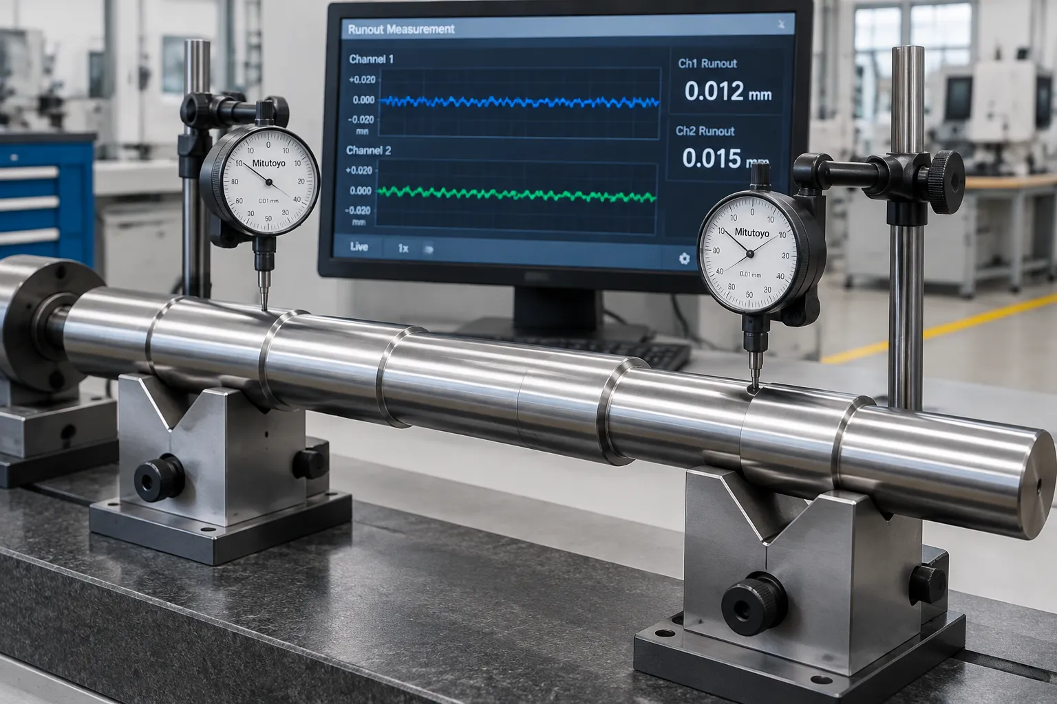
Concept illustration: separate measurement tracks for bearing, seal, coupling and impeller-fit journals; acceptance values and probe locations require the drawing and gauge-correlation study.
Control Long-Shaft Support and Self-Weight
Rotating-equipment service literature repeatedly notes that pump shafts are slender and prone to both bend and twist, and a long multistage or vertical-pump shaft deflects under its own mass during inspection. The measurement plan therefore freezes: shaft orientation; support type and spacing; rotation drive and contact force; probe force or non-contact sensor range; overhang at both ends; temperature and stabilization time; whether a sag-correction model is permitted; and the released-part dwell and remeasurement method.
More supports are not automatically better. A support parked on the wrong journal masks the true bend map, distorts a thin section or fabricates a measurement condition that never exists in the installed pump.
Build a Protected Contact Map
Every drawing review should end in an explicit support and press map.
Default no-press, no-support zones
- mechanical-seal running surface;
- finished bearing journals unless validated protective tooling exists;
- threads, keyways and splines;
- impeller, sleeve and coupling fits;
- shoulders, undercuts and fillet radii;
- oil holes, cross holes and thin transitions;
- coated, plated, repaired or corrosion-damaged areas;
- balance features and identification marks;
- assembled impellers, bearings, sleeves, seals or couplings.
Potentially approved zones
- plain shaft lands identified on the drawing;
- sacrificial machining allowance before final grinding;
- validated protective sleeves over approved lands;
- dedicated support journals designed for the process.
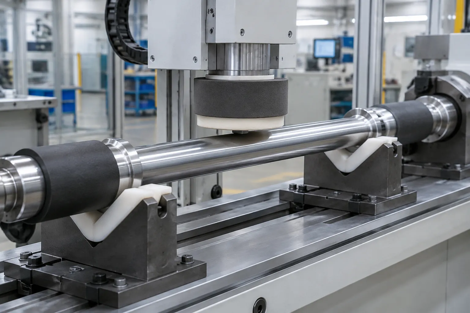
Concept illustration of approved contact lands with protected finished surfaces; the sleeves represent project-specific protection, not a universal tooling design.
Protective tooling has to do more than prevent visible dents. It must also control local contact stress, slipping, contamination transfer and the false measurements the sleeve itself can introduce.
Choose the Straightening Route Honestly
Closed-loop press straightening
Measure, predict, load, release, measure again. This is the right route when the shaft offers approved support and press lands and the material response has been validated. It is the architecture behind the shaft-type parts straightening machine family.
Roller straightening
Roller platforms suit constant-diameter shafts and bar-like parts; equipment suppliers in this space explicitly scope their standard roller machines to constant diameters. A stepped pump shaft needs a different fixture and measurement concept, not an optimistic roller setting.
Heat or peening repair
Heat spotting and peening are legitimate service-centre processes for pump shafts, with their own metallurgy, residual-stress and inspection controls. They are specialist repair routes, not default functions of an automatic cold-press cell.
Replace or re-machine
Straightening must not rescue a shaft with cracks, corrosion loss, damaged seal surfaces, exhausted grinding stock or an unapproved repair history. A controlled NOK route is part of the solution.
Control Springback and Cross-Coupling
Pump shafts usually carry several diameters and stiffness transitions, so a correction at one span can move runout at another bearing or seal journal. A production recipe works through: baseline angular map; conservative first correction; complete unloading; released-part remeasurement; updated response estimate; bounded repeat correction; a maximum-attempt or force stop rule; final inspection after the agreed dwell.
The target is never a pretty number on the display while the ram is loaded. It is stable geometry after release.
Straightening Is Not Alignment and Not Balancing
| Control | Main question | Typical stage |
|---|---|---|
| Bare-shaft straightening | Are the functional journals on the required axis? | Before final rotor assembly or grinding |
| Coupling alignment | Are pump and driver axes positioned correctly in the system? | Installation or maintenance |
| Rotor balancing | Is mass distribution acceptable at operating speed? | After rotating parts are assembled |
| Clearance verification | Do impeller, wear-ring and casing clearances hold? | Assembly and functional inspection |
| Seal inspection | Is the seal surface and installed motion acceptable? | Shaft and assembly inspection |
A straight bare shaft does not prove an aligned, balanced pump. Conversely, coupling misalignment or hydraulic loading should never be diagnosed automatically as a bent shaft.
The Closed-Loop Process, Ten Steps
- Identify the shaft. Part number, revision, pump family, material, heat-treatment state, process stage.
- Inspect and clean. Centres, journals, threads, keyways, coating, corrosion, cracks, previous repairs; remove anything that can distort the map.
- Qualify the datum setup. Centres or support journals, spacing, overhang, rotation drive, customer-gauge correlation.
- Measure all functional tracks. Angular runout waveforms at bearing, seal, impeller, sleeve and coupling locations per the control plan.
- Classify the signal. Global bend versus local form, setup error, self-weight sag, assembly deviation.
- Select an approved load path. Supports and press lands from the contact map; block any correction crossing a protected feature.
- Correct incrementally. Bounded force or displacement, response recorded; never transfer a recipe between materially different families without validation.
- Release and remeasure. Full unload, required dwell, complete functional-journal map rebuilt.
- Inspect the surface. Contact marks, coating, threads, keyways, seal surfaces, crack or surface checks where specified.
- Route the shaft. Pass, repeat within limits, grind or inspect, or reject, with the record preserved for traceability.
What a Pump Shaft Cell Can Contain
- manual, robot or gantry loading;
- part identification and recipe control;
- centre, V-support or roller support modules;
- adjustable outboard supports for long shafts;
- multiple contact or non-contact runout sensors;
- angular indexing and waveform acquisition;
- servo-electric or hydraulic correction axis;
- interchangeable protected support and press tooling;
- force and displacement monitoring;
- released-part remeasurement;
- pass / rework / NOK routing;
- SPC, traceability and data export;
- safety enclosure and controlled access.
Final architecture depends on shaft geometry, material, stage, tolerance, volume, upstream and downstream flow and plant requirements. No universal machine range or cycle time deserves quotation before those inputs are reviewed, a rule that applies to gearbox shaft straightening just as much as to pump work.
Sample Test and Acceptance Gates
| Gate | Evidence | Pass rule |
|---|---|---|
| Drawing review | Feature, datum, tolerance and contact-zone map | Engineering and customer approval |
| Incoming inspection | Repeatable baseline waveform on all required tracks | Setup variation within the agreed measurement study |
| Correction trial | Force, displacement, angle and released response | No prohibited contact, stable correction behaviour |
| Surface gate | Visual or specified surface inspection | No unacceptable marks or damage |
| Geometry gate | Released runout and straightness results | Customer-defined values under the agreed setup |
| Process capability | Representative samples across the incoming bend range | Agreed capability and rework limits |
| Gauge correlation | Machine versus customer inspection | Agreed correlation and dispute rule |
| Downstream check | Grinding stock, assembly, seal, clearance, balance result | Project-specific functional acceptance |
| Traceability | Recipe, part ID, measurements, correction history | Complete retrievable record |
Data Required for a Technical Proposal
- 2D drawing and, where available, 3D model;
- pump type, bare-shaft or assembled-rotor status;
- material, heat treatment, hardness, coating;
- shaft length, weight, all functional diameters;
- bearing, seal, impeller, sleeve and coupling features;
- centre-hole and support-journal details;
- drawing datum and customer inspection setup;
- runout or straightness limits per required track;
- incoming bend distribution and angular maps if available;
- approved and prohibited contact zones;
- surface, crack and corrosion acceptance rules;
- grinding stock and downstream operations;
- throughput, automation and traceability requirements;
- plant voltage, safety and line integration;
- representative good, borderline and NOK samples.
Frequently Asked Questions
Can a pump shaft be straightened?
Often yes, when material, process stage, bend pattern and approved contact zones support a validated correction. Cracked, worn or assembled shafts belong with another method or a replacement.
Which journals define pump shaft runout?
The bearing-related axis is usually central, but the pump design and the customer drawing decide. Seal, coupling and impeller-fit journals are measured as separate functional tracks.
Can the machine press on a mechanical-seal surface?
Not by default. Finished seal surfaces are protected zones unless a drawing-based tooling and contact-stress study explicitly approves contact.
Is a roller straightener suitable for a stepped pump shaft?
Not automatically. Standard roller platforms are built for constant diameters; a stepped pump shaft needs dedicated supports, localized press correction and multi-track measurement.
Can grinding remove pump shaft runout?
Grinding corrects local geometry and finish, but it should not be trusted to restore a bent functional axis while preserving stock and fits. Straightening and grinding are planned together.
Does a straight shaft eliminate pump vibration?
No. Alignment, balance, hydraulic forces, bearing condition, looseness, fit errors and operating conditions all contribute independently.
Can an assembled pump rotor be press-straightened?
Only after a separate study. Impellers, sleeves, bearings, seals, interference fits and balance features change both the signal and the safe load path.
Is a universal tolerance or cycle time guaranteed?
No. Those values depend on geometry, material, incoming bend, measurement method and validation results, defined through drawing review and representative sample testing.
Build the Solution Around the Pump’s Functional Axis
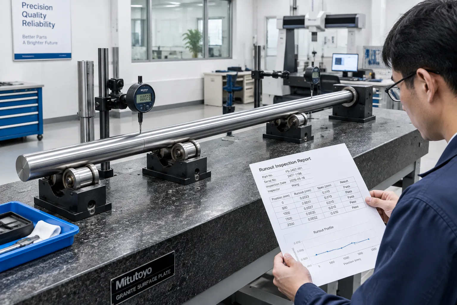
The right pump shaft straightening machine is not chosen from length and diameter. It is engineered around the pump family, the process stage, the functional datum chain, the protected surfaces, the material response, the released geometry and the downstream rotor checks. Send the shaft drawing, inspection method, incoming bend data and representative samples, and the support strategy, sensor tracks, correction route, tooling, trial plan, acceptance rules and automation scope follow as one controlled solution.
A Note on Compressor Shaft Straightening
There is no separate canonical page for the generic query “compressor shaft straightening solution” on this site: SERP evidence for that phrase maps mostly to general shaft-equipment pages rather than a distinct workpiece family. Use this page and the shaft-type parts overview for datum selection, correction zones and acceptance boundaries, and confirm the compressor stage, bearing span and inspection method on the drawing before quoting capability.