
Every motor shaft has to spin true. When bending creeps in after heat treatment, machining, grinding or even rough handling between operations, the consequences surface quickly: grinding chatter, tight assemblies, premature bearing wear and a motor that runs hot and loud. Straightening is how shaft producers pull those parts back into tolerance instead of scrapping them.
This solution outline is built around a real enquiry from an Indian manufacturer of motor shafts ranging from 8 to 18 mm in diameter and 140 to 600 mm in length. The plant still straightens every shaft by hand today and wants a documented final straightness of 0.05 mm. A UBS 300 automatic machine is the starting concept, but as with any shaft family, the measuring datum, the acceptance definition and the guaranteed result all have to be locked down from drawings and sample tests before anyone signs off on numbers.
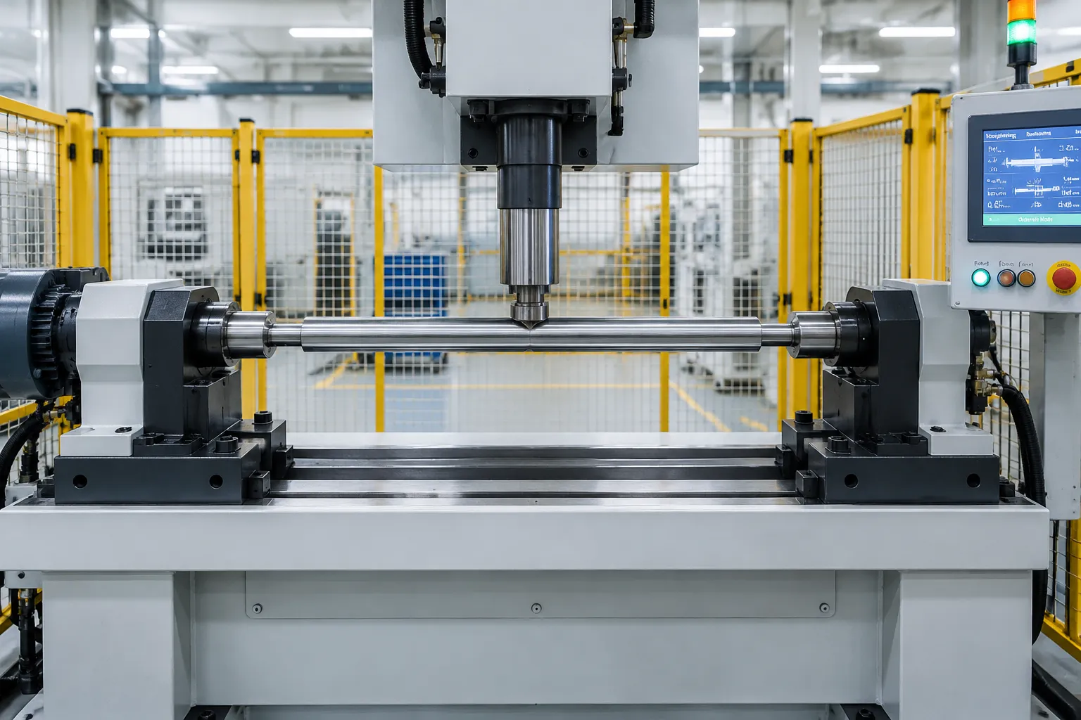
Engineering concept illustration. The station shown is a working principle, not evidence of a specific customer installation or a guaranteed result.
The Workpiece and What the Customer Actually Asked For
A motor shaft carries the rotor and delivers torque to whatever the motor drives, whether that is a gearbox, a coupling, a fan or a pump. Along its length sit bearing journals, rotor seats, shoulders, grooves, keyways, splines or threaded ends. Which of those surfaces define the true running axis decides how the shaft must be measured, supported and pressed, so the drawing review comes before any machine talk.
The 0.05 mm figure in this project is the customer’s stated requirement, nothing more. It cannot be advertised as a universal UBS 300 capability until three questions are answered: does the drawing control straightness, radial runout or total indicated reading; where exactly is the measurement taken; and which journals or centres act as the datum. General background on shaft workpiece families is covered in the overview of shaft-type straightening machines.
| Project Item | Customer Input / Status |
|---|---|
| Workpiece | Motor shaft |
| Diameter range | 8-18 mm |
| Length range | 140-600 mm |
| Current process | Manual straightening |
| Requested result | 0.05 mm straightness; definition and datum to be confirmed |
| Material and hardness | Not yet provided |
| Process stage | Heat treatment / machining / grinding stage to be confirmed |
| Proposed equipment | UBS 300, subject to engineering and sample validation |
| Loading | Automatic feeding demonstrated on video; production rate to be confirmed |
| Protected areas | Bearing journals, rotor seats, threads, keyways, finished surfaces |
Straightness, Radial Runout and TIR Are Three Different Questions
These terms get used interchangeably on shop floors and it costs real money. Straightness asks how far the shaft axis wanders from a perfect line. Radial runout asks how much a probe deflects while the part rotates about a defined datum. Change the datum, from centres to bearing journals for instance, and the same shaft produces a different runout number. A machine that hits one definition will not automatically satisfy another, so the shop and the customer’s final inspection must agree on the same reference before the tolerance means anything.
Practically, the drawing needs to name the controlled characteristic, the tolerance zone, the datum features and the measuring positions. If the assembled motor locates the shaft on two bearing journals, those journals, not some arbitrary outside diameter, are the meaningful reference. Measuring points should stay clear of keyways, grooves and diameter changes unless the method is explicitly designed to ride over them.
| Control Item | What Must Be Defined |
|---|---|
| Datum | Centres, bearing journals or named reference diameters |
| Measuring points | Axial positions and diameters stated on the drawing |
| Incoming bend | Maximum and typical distribution before straightening |
| Final tolerance | 0.05 mm target; confirm straightness or TIR interpretation |
| Surface condition | Ground, turned, hardened or coated |
| Acceptance | Machine result, customer gauge correlation, sample capability study |
Why Motor Shafts Resist a Simple Fix
A 140 mm shaft and a 600 mm shaft from the same family behave like different animals. Stiffness, sag between supports and the correction stroke they need all change with the length-to-diameter ratio, so one fixed press recipe cannot be assumed to serve the whole range. Each model deserves its own validated support positions and correction limits.
The geometry compounds the problem. Lean a shaft on a shoulder, park a probe over a groove or press across a finished journal and the machine either reads a bend that is not there or leaves a mark that rejects the part downstream. Push too hard and the bend reverses or stress concentrates at a keyway root. Material, hardness and heat-treatment history therefore belong in the quotation package, not in a later surprise.
| Challenge | Risk | Engineering Control |
|---|---|---|
| Wide length and diameter span | Wrong support span or correction response | Model-specific support positions and recipes |
| Unknown material condition | Unpredictable springback, crack risk | Material and hardness confirmation plus sample tests |
| Several functional journals | Measuring the wrong axis | Drawing-based datum and measuring-point selection |
| Keyways, grooves, threads | Stress concentration, false probe signals | Protected no-press zones, approved measuring surfaces |
| Finished surfaces | Support or press marks | Contoured contact, correct contact materials, cleanliness |
| Manual process variation | Operator-dependent results | Automated measurement, controlled correction, rechecks |
Choosing the Process: Point Press, Not Rolls
For discrete, stepped motor shafts with defined journals, automatic point-press straightening is usually the right architecture. The machine can rotate and measure the shaft, compute where and how much it bends, index it to an approved correction point, deliver one measured over-bending stroke, and look again. A continuous roller machine, by contrast, keeps sweeping the whole part and is happiest on constant-diameter bar or uniform blanks. Rolls will happily ride across keyways and finished journals on a stepped shaft, which is exactly what a motor shaft cannot afford.
That is a selection rule, not dogma. Uniform shaft blanks can still pass through a roll machine before finishing, and some low-volume shops keep manual benches as backup. The decision belongs to the shaft family on the drawing, not to the product catalogue name.
The Automatic Cycle, Step by Step
The reference video for this project shows slender shafts entering an automatic feeder and settling into the straightening station. It is useful evidence of material flow and pressing concept; sensors, force range, cycle time and model coverage still have to be matched to the drawing set.
1. Part identification and recipe call-up
Each shaft model has a validated recipe: length, reference diameters, support positions, measuring points, permitted correction zones, target tolerance and stroke limits. Where mixed models run on one line, barcode or DMC selection keeps the operator out of the decision.
2. Feeding and positioning
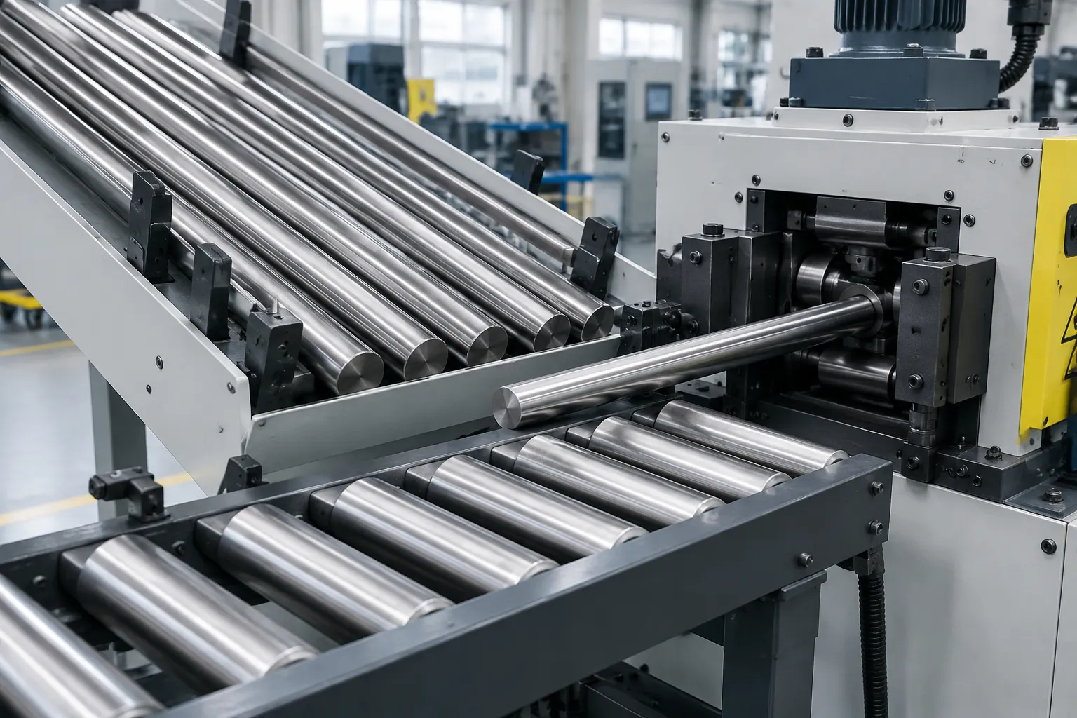
Engineering concept illustration; feed geometry and part separation are sample-validation items.
The feeder singulates shafts and places each one on approved support zones. Rails, pockets and contact materials have to suit the 8-18 mm range without scratching finishes or letting two parts enter together. During rotation the fixture holds the shaft axially stable while keeping contact off keyways, threads and bearing surfaces.
3. Rotating measurement
The shaft spins while sensors record deviation at the specified axial positions. Probe type, contact force and filtering match the surface condition, and plausibility checks catch dirt, grooves or a diameter step faking a bend that does not exist.
4. Bend calculation and angular indexing
The controller resolves bend magnitude and clock angle, picks a safe axial press point and rotates the high side under the ram. Multi-bend shafts need a validated press sequence so one correction does not manufacture a new error somewhere else along the part.
5. Controlled over-bend
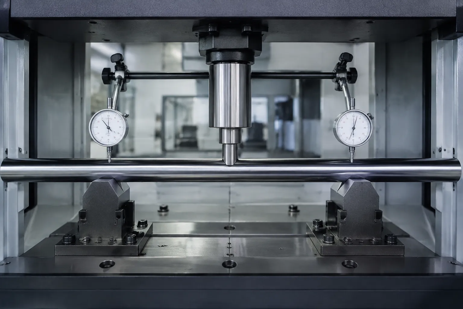
Engineering concept illustration of one controlled correction stroke.
Straightening works by bending slightly past straight and letting elastic springback settle the shaft near zero. The stroke depends on diameter, local section, material and hardness, which is why first limits are set conservatively on samples and refined from measured response. Stroke ceilings and, where fitted, force monitoring stand guard against over-correction, cracking and dented surfaces.
6. Remeasure and adapt
Same datum, same points, fresh rotation. If the shaft is still outside target but inside validated limits, the controller computes the next correction. A maximum cycle, stroke or force count stops the machine from thrashing a part that will not cooperate.
7. OK/NOK decision and unloading
A part is accepted only when every required point passes the confirmed criterion. Inconsistent readings or a part that exhausts its correction budget goes to NOK or manual review, and where traceability matters the machine logs before/after values, press count, recipe and result.
Cell Configuration Proposed for This Project
| Module | Proposed Requirement |
|---|---|
| Base machine | UBS 300, capacity subject to confirmation |
| Workpiece range | 8-18 mm diameter, 140-600 mm length for this project |
| Measuring system | Contact displacement or equivalent validated runout measurement |
| Rotation | Controlled rotation on approved shaft datum |
| Straightening unit | Fine-stroke press with model-specific limits |
| Supports and tooling | Adjustable, protected contact across the length range |
| Feeding | Automatic separation, transfer, unloading per project video |
| Controls | HMI recipes, correction calculation, remeasurement, OK/NOK logic |
| Data | Optional before/after values, correction count, traceability |
| Safety | Guarding, interlocks, overload and abnormal-measurement alarms |
Validation Comes Before the Quotation Promise
Nothing on this page is a performance claim yet. Sample parts should span the family: shortest, longest, thinnest, thickest, plus normal and worst-case incoming bends, and any material or heat-treatment batch variation. The report that comes back should record datum, incoming values, final values, press counts, cycle time, surface condition and every rejected sample.
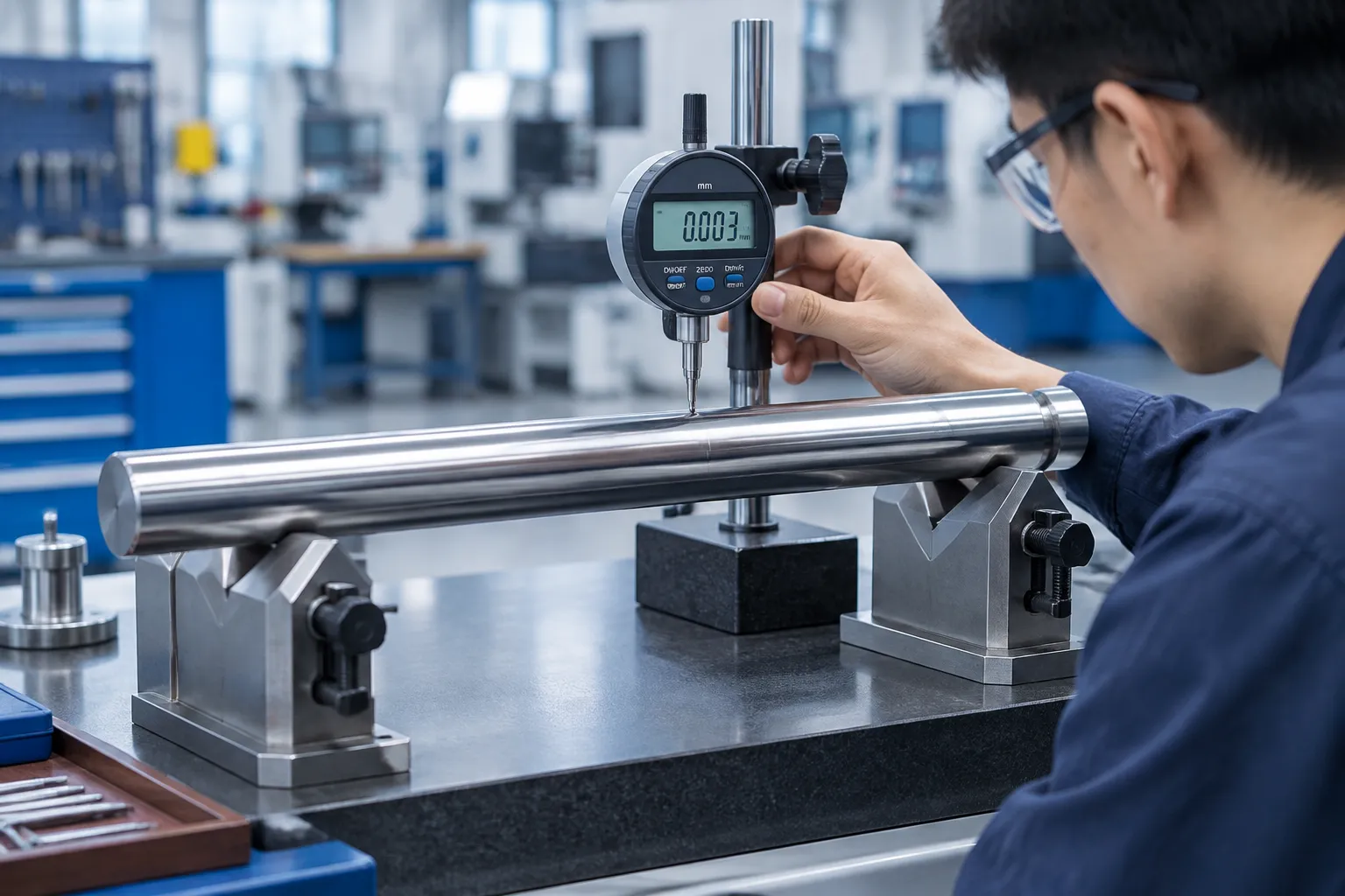
One check deserves special weight: correlating the UBS 300’s measurement with the customer’s own inspection method. Until both gauges agree, the 0.05 mm target is a intention, not an acceptance criterion. Similar care applies across the wider shaft family; the same logic is described for electric motor rotor straightening and for gearbox shaft straightening, where stacked components and gear datums add their own constraints.
Information to Prepare for a Proposal
A usable enquiry package for a motor shaft line contains: shaft drawings, material and hardness, heat-treatment stage, minimum and maximum dimensions, bearing and rotor-seat locations, keyway and thread positions, incoming bend distribution, final tolerance and its definition, inspection datum, allowed support and press areas, target cycle time, annual volume, loading direction and representative samples.
With those inputs the engineering team can confirm whether one UBS 300 covers the entire 8-18 mm by 140-600 mm family or whether the project needs change tooling, extra supports or a different machine concept altogether. For very small or very slender shafts, a compact alternative is the automatic small shaft straightening machine rated to 0.02 mm.
Frequently Asked Questions
Can the UBS 300 guarantee 0.05 mm on every 8-18 mm shaft?
Not from diameter and length alone. The outcome depends on material, hardness, geometry, incoming bend, datum and measurement definition, which is exactly why drawing review and sample tests come first.
Can one machine really span 140 to 600 mm shafts?
It can, provided machine travel, supports, sensors and press positions cover the full range. Every model still needs its own validated recipe, and some changeover tooling should be expected.
What does automation change versus the manual bench?
Feeding, measurement, correction limits, rechecks and sorting become standardized and repeatable. People still run material supply, audit inspections, tooling maintenance and the occasional abnormal part.
How are journals and finished surfaces protected?
The drawing defines where supporting, measuring and pressing are allowed. Contoured contacts, appropriate contact materials and clean fixtures keep marks below the rejection threshold.
What happens to a shaft that will not reach the target?
Once the validated correction, stroke or force limit is exhausted, the machine stops pressing and routes the part to NOK or manual review rather than hammering away at it.
What is the minimum input for an accurate quotation?
Drawings, material and hardness, incoming and target measurement, inspection datum, protected features, production volume, target takt time and sample parts. Anything less produces guesswork with a price tag.
Summary
Motor shaft automatic straightening is a closed loop: measure, correct a known amount, measure again, decide. For this 8-18 mm and 140-600 mm project the engineering decisions that matter are the functional datum, an adjustable support strategy, model-specific correction response and a verified reading of what 0.05 mm really means on the customer’s drawing.
Send shaft drawings, incoming bend data, target tolerance, volume and samples for a UBS 300 feasibility review. The final proposal should stand on sample evidence and an agreed acceptance method, never on diameter and length alone.