
A gear shaft carries gear teeth, journals, splines, threads and shoulders on one rotating axis, and its straightness specification lives on that axis: the journals and the gear pitch cylinders must rotate about a common line inside a total-indicator-reading limit set by bearing life, mesh quality and shaft speed. Straightening a gear shaft is therefore not the same job as flattening a toothed bar. It is a rotational measurement problem with well-established correction methods, and it rewards whoever maps the bend before touching the part.
Five questions decide the solution before any equipment is chosen:
- What defines the measurement axis: journals, centres or a spline major diameter, and does that survey reflect how the bearings actually support the shaft in service?
- Is the deviation a single-plane bow, a local bend at a shoulder, a twist, or a combination, and where is the true high point?
- What is the material state: through-hardened, carburized and quenched, or induction-hardened journals, and which correction routes are approved for it?
- Is grinding stock still available, and is the correction meant to recover stock distribution or final geometry?
- How will released geometry, tooth-flank integrity and long-term stability be verified?
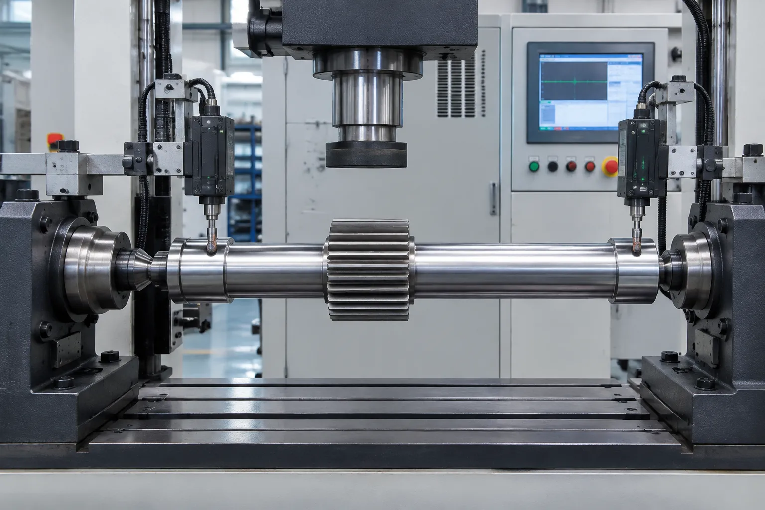
Engineering concept illustration: a gear shaft between centers with probes on the journals. Not a customer-site photograph; datum choice, force positions and acceptance limits come from the drawing and sample parts.
Gear Shaft or Gear Rack? Two Different Problems
Both workpieces have teeth, and they get confused constantly. In engineering terms they share almost nothing. The rack is covered separately on the gear rack straightening machine page; the short version of the split is this table:
| Gear rack | Gear shaft | |
|---|---|---|
| Function | Turns rotation into linear motion; toothed straight bar | Transmits torque between rotating axes; toothed cylindrical part |
| Straightness definition | Flatness and straightness of a reference surface in one plane; pitch-line flatness | Deviation of the rotation axis: TIR around the circumference at defined sections |
| Primary measurement | Linear: straightedge, surface plate, laser line, length-wise sampling | Rotational: rolled between centers or on journals, dial or electronic probes, bend survey map |
| Failure when bent | Binding, uneven tooth engagement, positioning error | Unbalance, vibration, bearing and seal damage, mesh misalignment, fatigue |
| Typical correction | Pressing in the flat plane; leveling for long rack stock | Point-press at the mapped high point, selective peening, restricted heat methods |
A rack is corrected in a plane; a gear shaft is corrected around an axis. Fixtures, vocabulary, machines and acceptance criteria all differ. If the part is a long toothed bar meshing with a pinion to move a load linearly, the rack page is the right one. If it is a shaft with a gear on it that spins in bearings, read on.
Anatomy and Where the Distortion Comes From
The features that matter form the datum chain and the stress system at once: bearing journals as the primary functional axis; gear segments with their face width, pitch and root geometry; splines, keyways, threads, tapers and coupling features; shoulders, snap-ring grooves, cross-drillings and oil holes; process centres; and whatever grinding stock remains, section by section.
Gear shafts bend for the classic reasons the repair literature documents: mechanical overload in handling or assembly; asymmetric machining that relieves residual stress unevenly; heat treatment, where quenching a carburized or through-hardened shaft nearly always introduces bow; and heavy shrink or press fits that bow an initially straight shaft as a stack. Two gear-specific effects add on top: hobbing and shaving leave residual stress locked around the toothed sections, and grinding one journal after heat treatment can relax stress and shift a different section. The placement of the correction step in the process routing matters as much as the correction itself.
Measure First: The Bend Survey Map
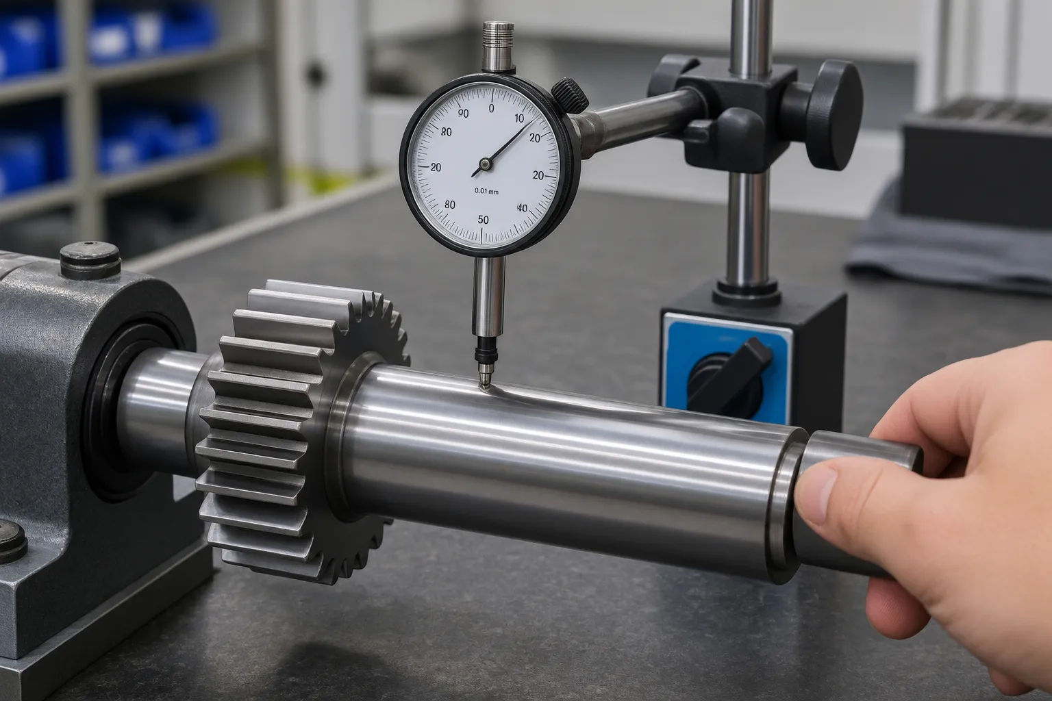
The old repair-shop discipline of mapping a bent shaft before correcting it carries straight into automated production:
- Support the shaft between centres or on its journals and verify the supports themselves read zero runout, because support error poisons the whole map.
- Mark a rotational reference, then record TIR at evenly spaced axial stations, converting to deflection, half of TIR, and clock angle at each one.
- Interpret the map: one dominant high point at a consistent angle means simple bow; an angle that rotates along the length means multiple bends or twist; combined bend and twist is the hardest case.
- Find the true high point between stations, since the maximum sits where the trend says, not necessarily where a probe happened to rest.
- Repeat the map after every correction cycle and once more at the end as the inspection record.
Two traps hide in this step. First, datum choice: on a stepped gear shaft the correct datum chain is usually the journals, not the centres. A shaft can read straight on centres and bowed on journals, and the bearings do not care about the centres. Second, tooth-flank error versus bend: pitch-cylinder runout measured over pins or on a gear checker must be separated from shaft-axis runout, or a tooth-manufacturing error gets treated by bending the shaft, which fixes nothing and risks the teeth.
Correction Routes
Point pressing: the primary route
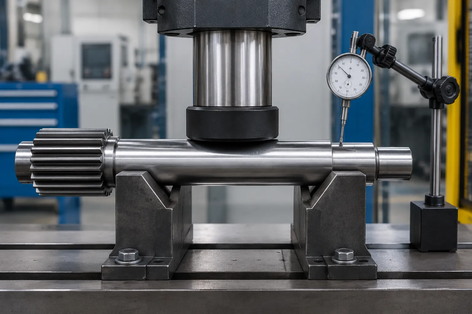
With the map in hand, the shaft is set high point up, supported close to the bend, and loaded by a padded ram while a probe watches live deflection. Small strokes, springback accepted: the goal is the fewest corrections to tolerance, because every plastic cycle adds residual stress. On production machines the map-press-remap loop runs automatically, with springback compensation learned per part family. Automation relocates the craft skill into controller parameters; the physics stays the same.
Peening: where a ram cannot reach
Controlled shot or needle peening on the concave side compresses surface fibres, grows them slightly and pulls the axis toward straight. On gear shafts peening is the fine-trim tool: it removes small residuals after pressing and works beside shoulders and near toothed sections, with no chance of crushing teeth. It is slow per correction and almost never the primary route.
Spot heat: heavily restricted on hardened shafts
Spot heating a small zone to create local tensile stress on cooling is a legitimate method for low- and medium-carbon shafts in the unhardened state. On carburized, through-hardened or induction-hardened gear shafts it is restricted or prohibited outright: the heat-affected zone can soften or re-harden local material and seed microcracks exactly where tooth and journal fatigue life is spent, and it can leave a raised bump that has to come off before the surface runs in a bearing or seal. Where heat methods are considered at all, they belong to a metallurgist-approved repair procedure, never to a production correction cycle.
What pressing a gear shaft never includes
Loads go on journal or plain shaft-body sections between supports, never onto gear teeth. Pressing the toothed segment risks tooth deformation that no straightening can undo, and roll-straightening of the kind used on plain shafts is not applied over teeth at all. Spline sections follow their own acceptance logic, discussed for the spline shaft straightening machine, and the input, output and intermediate shafts inside gearboxes, with their multi-journal acceptance chains, are treated in the gearbox shaft straightening solution.
Acceptance Criteria
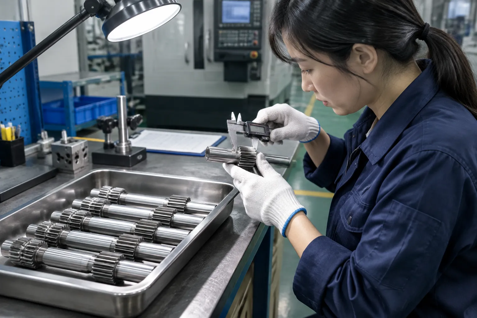
Repair practice offers a usable baseline: roughly 0.001 in per foot of length, 0.083 mm per metre, for general rotating equipment, tightening toward 0.0005 in, about 0.013 mm total, at any point for high-speed multi-stage machinery. For gear shafts the drawing governs, and the tolerance class follows the application: a low-speed, wide-clearance gear shaft carries a more generous window than a high-rpm close-clearance pinion. A complete acceptance sequence looks like this:
- final survey map at all stations inside the specified TIR;
- gear quality checks, tooth contact, runout over pins, helix alignment, unchanged by the correction;
- crack detection appropriate to the material condition, performed after all correction;
- verification after the final grinding or finishing operation, not only after straightening;
- stability confirmation for critical applications: re-measure after a standing interval or temperature cycle unless the process window has already proven stability.
The last point is the honest weakness of all shaft straightening: a correction that merely stacks new stress against the old bend can read straight today and drift in service. That is why correction counts are capped, why the map is repeated after finishing, and why the number of strokes to tolerance is itself a process-quality signal, the same principle applied line-wide in motor shaft automatic straightening.
Common Pitfalls
- Mapping on the wrong datum. Centres that no longer represent the bearing axis produce a map that cannot be corrected into a functioning shaft.
- Pressing at a station instead of the high point. Maximum deflection usually lies between probe stations; find it before loading.
- Loading teeth or hardened splines. Ram force belongs on plain sections; teeth deform permanently and invisibly to the TIR map.
- Chasing twist with single-plane presses. Combined bend-and-twist needs a planned sequence, not repetition of one stroke.
- Trusting only the post-press reading. Residual stress redistributes; the release check belongs after final grinding, and the field result after that.
Separating Bend From Twist Before Choosing a Sequence
The survey map decides not only whether to correct but in which order. Three diagnostic signatures cover most gear shafts:
- Simple bow: deflection magnitudes rise and fall along the length at a consistent clock angle. One press at the mapped high point, springback learned, done. The easy case, and the one manual practice handles acceptably.
- Two-plane or S-bend: the clock angle rotates along the length. Two corrections are planned in sequence, each verified on a fresh map; clearing the larger bend first usually simplifies the second.
- Bend with twist: angular features, splines, keyways, gear phase relative to the journals, show torsional displacement on top of the bow. Pressing treats the bend and leaves the twist; twist correction is a separate operation with its own validation. Shafts that pass TIR and fail phasing come from pretending otherwise.
Automatic machines make the first two cases routine: the controller fits the measured stations, computes press position, overstroke and support spacing, and closes the loop in two or three cycles. The twist case remains the one that separates a serious process definition from a press with software, and it is exactly what the five opening questions are designed to catch before the shaft burns its correction budget on strokes aimed at the wrong mode. The same machine family also covers non-toothed rotating parts; see the shaft-type parts straightening overview.
What a Serious Inquiry Contains
A gear shaft straightening machine or cell is specified from: the drawing with its datum scheme and TIR limits by section; material and heat-treatment state at the point of correction; gear data, module, helix angle, hardness, so that loading exclusions are explicit; the current distortion distribution at the measurement station; sample parts across the deviation range; cycle-time and traceability requirements; and the rework-limit policy. From those inputs the support-and-probe plan, press force class and springback-learning strategy follow directly, and the station can be validated against parts rather than promises. Closely related shaft families, from long transmission shafts to drive shaft straightening, follow the same specification discipline.