

A gear rack straightening machine has to correct more than one flat face: an industrial rack can bend vertically, bend laterally, and twist along its length—all in the same part—and still pass a naive back-face check while meshing badly with its pinion. This page gives the tested machine specification and trial video first, then the complete engineering layer of industrial gear rack straightening: datum hierarchy, tooth protection, twist correction, joint-pitch alignment, and the acceptance boundary between free rack geometry and installed mesh.

Tested Specification and Machine Video
The tested rack family: 25 mm width x 8 mm thickness x 800 mm length, required straightness 0.1 mm, corrected on an AMS-PS1000 gear rack straightening machine. The rack is straightened on all four planes: the machine automatically changes the rack position between correction passes, so vertical bend, lateral bend, and twist are each corrected in their own setup without manual re-clamping. The line runs with an auto loading belt and auto unloading belt; the PLC and touchscreen store the straightness target per workpiece recipe.


Why Industrial Gear Racks Need a Dedicated Solution
An industrial gear rack is a toothed transmission component, not simply a rectangular bar. Its flat back, side datum, tooth line, mounting holes, joint ends, and heat-treated regions must work together with the pinion and the machine base. A rack can be straight on its back face yet twisted along its length, or meet a body-straightness check while still producing poor tooth contact at installation:
| Rack Feature | Straightening Risk | Project Response |
|---|---|---|
| Long rectangular or square body | Can bend vertically and laterally | Measure both principal directions along the usable length |
| Teeth on one face | Tooth tips and flanks are functional, damage-sensitive features | Keep teeth outside support, clamp, and press load paths |
| Straight or helical teeth | Tooth direction changes feature sensing and joint alignment | Use tooth-form-aware measurement and model-specific recipes |
| Back and side mounting faces | These surfaces often establish installation geometry | Define drawing datum, machine support, and customer base separately |
| Torsion | One end can rotate relative to the other | Measure angular orientation by station and correct torsion separately |
| Hardened tooth zone | Correction may crack or damage a locally hardened region | Map hardness/case and restrict load zones through sample testing |
| Mounting holes and joints | Holes interrupt measurement; joints require pitch continuity | Mask discontinuities and verify joint/interface geometry independently |
| Pinion mesh | Body straightness alone does not prove backlash or tooth contact | Add installation or master-pinion correlation where required |
The objective is not to force the rack against one straight reference. The objective is an approved relationship between its body datums, tooth line, joint ends, and installed drive system.
Keep Industrial Rack Separate from Steering Rack and Guide Rail
| Workpiece | Main Geometry | Dedicated Engineering Content |
|---|---|---|
| Industrial gear rack | Long rectangular/square bar with straight or helical teeth | Back/side datum, tooth-line geometry, bend, twist, joint pitch, and mesh |
| Automotive steering rack | Round or Y-shaped shaft with a local toothed zone and end journals | Automotive rack-shaft datum, local tooth-zone sensing, and journal relationships |
| Linear guide rail | Profiled rolling-contact rail with raceways and mounting holes | Guide datum faces, raceway protection, full-length bend/twist, and carriage installation |
This page is for machine tools, automation systems, gantries, lifting and handling systems, and other industrial rack-and-pinion applications. Automotive steering racks and linear guide rails are separate workpiece families with their own datum logic and should not share recipes with industrial racks.
Define the Rack Family Before Selecting Equipment
Industrial racks vary widely. A proposal should identify:
- straight-tooth or helical rack;
- rectangular, square, or profiled body;
- single-piece or jointed/segmented installation;
- soft, through-hardened, induction-hardened, or case-hardened condition;
- cut, milled, ground, or otherwise finished tooth form;
- top-, side-, or bottom-mounted orientation;
- drilled, counterbored, doweled, or clamp-mounted body;
- finished rack, semi-finished blank, or rack before final grinding;
- matching pinion, module or circular-pitch system, and accuracy requirement.
One recipe cannot safely cover every rack with the same module, because body section, hardness, tooth direction, hole pattern, and manufacturing stage change stiffness and safe contact zones.
Freeze the Manufacturing Stage
Rack blank before tooth cutting
The part behaves mainly as a profile bar. Later tooth machining, heat treatment, and grinding can introduce new distortion, so blank straightness is an intermediate control.
After tooth cutting, before heat treatment
Teeth already require protection, but the material condition may permit more correction than after hardening. Subsequent heat treatment still requires remeasurement.
After heat treatment
Heat treatment can produce bend and twist and change springback. The project needs material, hardness profile, case depth where applicable, crack risk, and permitted correction strain.
After tooth grinding or final finishing
The tooth flanks, tips, and mounting surfaces are finished functional features. Supports, sensors, and tools must not scratch, dent, or polish them, and correction limits normally become more restrictive.
Jointed rack installation set
Individual segments can pass a body check yet fail at the joint. Segment order, hand of helix, joint pitch, dowel location, and installed base alignment must be included in the validation route.
Define the Controlled Characteristics
Do not use “rack straightness” as one undivided acceptance value. The drawing may separately control:
- straightness or flatness of the back mounting face;
- straightness of a side datum face;
- vertical and lateral bend over local or full length;
- twist or angular change along the rack;
- parallelism or orientation between back and side datums;
- relationship between the pitch line/tooth direction and body datums;
- tooth profile, lead, pitch, and flank condition;
- mounting-hole position and joint-end geometry;
- segment-to-segment pitch continuity;
- installed backlash and tooth contact with the pinion;
- motion accuracy, noise, or vibration in the assembled axis.
Straightening can influence global body geometry and orientation. It does not automatically correct pitch error, tooth profile, heat-treatment damage, mounting-hole position, or pinion geometry.
Establish the Datum Hierarchy
The solution should distinguish five references:
- drawing datum surfaces that define the tolerance;
- physical supports used by the straightening machine;
- measured tracks used to calculate bend and twist;
- the mounting base and side reference used during installation;
- the pitch/mesh reference used with the pinion.
A rack may rest on its back face during inspection, but that does not mean every correction can safely load the same surface. Likewise, a stable machine fixture is not automatically correlated with the installed machine base.
Measure Body Geometry and Tooth Geometry Separately
The body and teeth carry different signals. Flat back and side faces are suitable for reconstructing released rack geometry when they are drawing-relevant and undamaged. Tooth flanks or pitch-related features require feature-aware measurement:
| Measurement Track | Main Output | Main Risk |
|---|---|---|
| Back mounting face | Vertical bend / flat-face curve | Support reaction, hole interruption, and surface contamination |
| Side datum face | Lateral bend | Burrs, local machining marks, and inconsistent seating |
| Two separated body tracks | Angular orientation / twist | Sensor coordinate mismatch or profile variation |
| Tooth-side reference | Tooth-line relationship to body | Tooth form can be mistaken for global bend |
| Joint ends | Segment alignment and step | End chamfer, damage, or wrong segment order |
| Master pinion or functional gauge | Mesh/contact correlation | Pinion error, mounting compliance, and backlash setup |
Full-length measurement should use drawing-based stations and mask holes, countersinks, chamfers, and discontinuities. For a helical rack, the tooth signal moves axially with the measuring position, so the algorithm cannot treat it like a continuous flat surface.
Control Support Influence and Free Movement
Long racks deflect under their own weight. Support number, spacing, height, and friction change the observed curve—too many rigid supports can over-constrain the rack, too few create excessive sag. The recipe should define:
- support coordinates and contact faces;
- rack orientation and tooth direction;
- free longitudinal movement during horizontal correction;
- sag treatment and temperature condition;
- loading and release sequence;
- support cleanliness and permitted contact pressure;
- correlation to the customer’s gauge or mounting base.
Published profile-straightening practice for square racks places the rack freely on supports, applies horizontal force, and scans continuously along the full length. The transferable principle: the rack must be measured and corrected without unintended clamping that hides its deformation.
Protect Tooth Tips, Flanks, and Hardened Zones
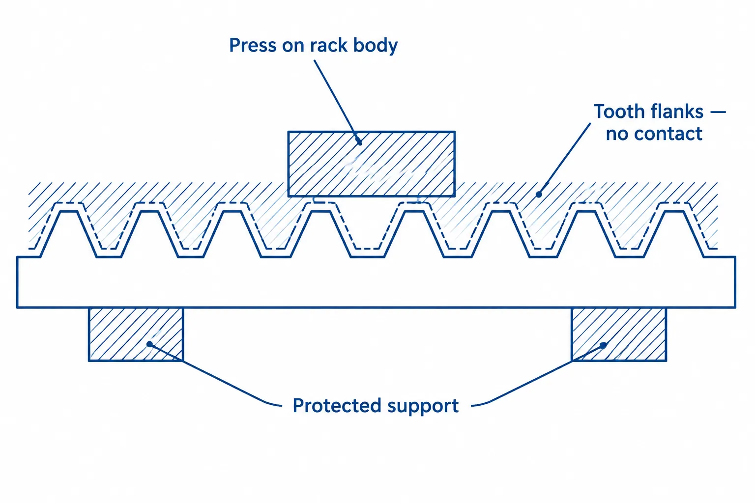
The tooth system should be treated as a protected functional region unless a drawing-approved feature gauge is used:
No tooth-tip supports
Narrow supports under tooth tips create local damage and unstable seating. Supports should contact approved flat body surfaces or dedicated sacrificial process lands.
No pressing through the tooth line
The correction shoe should not transmit bending load through tooth tips or flanks. Where the rack orientation places teeth toward the reaction side, the tooling needs a relief channel that leaves the teeth clear.
Controlled contact on finished datums
Broad clean pads can distribute force over approved back or side faces. Liner material, embedded particles, edge radius, and sliding behavior require validation.
Hardness and crack boundary
Induction or case hardening creates locally different ductility and residual stress. The rack drawing and heat-treatment route must determine whether correction is allowed near the tooth root or hardened transition, and sample testing should include appropriate surface and crack inspection.
Correct Vertical Bend, Lateral Bend, and Twist
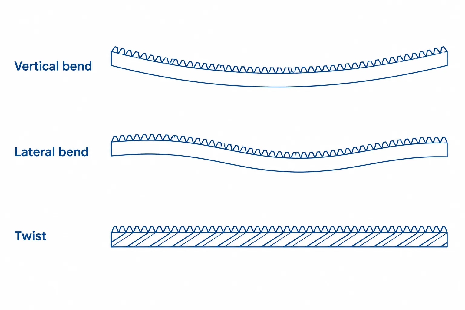
| Deviation | Measurement | Typical Correction Concept | Recheck |
|---|---|---|---|
| Vertical bend | Back-face height by station | Broad supports plus controlled load on approved flat face | Full vertical, lateral, and twist map |
| Lateral bend | Side-datum position by station | Horizontal point correction with free longitudinal movement | Full map and tooth/body relationship |
| Twist | Angular change between separated tracks | Profile-matched torsion heads over a selected span | Bend plus angular map after release |
Torsion straightening for racks, guide rails, and twisted profile bars is a dedicated process applied to one or more sections. Twist therefore needs its own measurement, clamping, and springback model rather than being treated as an incidental result of bending.
Preserve Rack Joint and Pitch Alignment
Long axes often use multiple rack segments, and body straightening cannot be accepted without a joint strategy. Rack manufacturers’ official installation guidance uses a joining rack or gauge for pitch alignment, then checks secure mounting, backlash, abnormal noise or vibration, and edge contact—these are installation controls, not automatic results of straightening. The project should define:
- segment identity and installation order;
- straight or helical tooth hand;
- joint-pitch alignment method;
- permitted step between back and side datums;
- gap or end condition according to the selected rack design;
- dowel/bolt sequence and mounting-base quality;
- pinion backlash and tooth-contact check;
- responsibility boundary between supplied rack geometry and customer installation.
Do not copy a gap or backlash value from another rack series; the approved value comes from the rack/pinion manufacturer’s drawing and installation procedure.
Recommended Closed-Loop Process
- Identify the rack — select the validated recipe from part number, section, length, tooth type, module/circular pitch, hardness, and process stage.
- Inspect and clean — check tooth damage, burrs, corrosion, cracks, incorrect holes, wrong segment identity, and other rejection conditions; remove chips from approved datum surfaces.
- Load on approved body surfaces — orient the tooth line and datums correctly; confirm seating without using the teeth as supports.
- Scan the full-length body geometry — measure back face, side datum, and angular orientation along the defined station map, masking holes and discontinuities.
- Evaluate the tooth/body relationship — use the approved feature method where tooth-line orientation or pitch-related alignment is controlled; keep tooth-form error separate from body bend.
- Select a safe correction mode — vertical bending, lateral bending, or torsion correction, with no-press/no-clamp zones for teeth, holes, hardened transitions, and joint ends. A profiled rack with discrete protected zones needs location-specific correction rather than an assumed through-feed process.
- Apply controlled correction — broad profile-matched tooling with force/displacement or torque/angle monitoring, limited by the validated material and hardness envelope.
- Release and remeasure — judge only the unloaded rack; remeasure every controlled direction because correcting one plane can affect another.
- Verify surface and joint requirements — inspect tooth flanks/tips, back and side datums, holes, and required crack criteria; for segmented systems, perform the defined joint correlation or functional gauge check.
- Record and unload — store rack identity, recipe revision, before/after maps, correction history, alarms, and disposition where traceability is required.
Free Rack Geometry vs Installed Mesh
| State | What It Demonstrates | What It Does Not Demonstrate |
|---|---|---|
| Free-supported rack | Released body bend and twist under a defined support model | Final base straightness, bolt effects, or pinion contact |
| Rack in inspection fixture | Geometry relative to a controlled fixture datum | Customer base and fastening behavior |
| Rack segments on machine base | Joint alignment under the installation sequence | Pinion accuracy or operating load behavior by itself |
| Rack with master/production pinion | Backlash/contact under the defined setup | Every operating speed, load, lubrication, or life condition |
The quotation and acceptance protocol must state which state is controlled by the straightening machine and which checks remain part of installation or system commissioning.
Proposed Cell Configuration
| Function | Project-Specific Configuration |
|---|---|
| Handling | Manual, assisted, portal, or automated loading based on rack length/mass |
| Identification | Barcode/data matrix or validated model selection |
| Support | Low-friction broad pads contacting approved back/side faces |
| Measurement | Multi-track full-length contact or non-contact scanning |
| Tooth feature check | Profile-aware sensor, master feature, or off-line gauge as specified |
| Bend correction | Horizontal/vertical press axes or controlled rack reorientation |
| Torsion correction | Integrated or separate profile-matched torque heads |
| Protection | Tooth-clearance channels, clean liners, and keep-out maps |
| Traceability | Before/after curves, correction history, and recipe revision |
| Safety | Guarding for long-part movement, press force, and stored torsional energy |
Sample Testing and Acceptance
The sample matrix should cover minimum/maximum section and length, straight/helical variants, material and hardness range, hole pattern, joint style, manufacturing stage, and the real incoming bend/twist distribution. Include typical and difficult parts rather than only selected easy samples. Acceptance should define:
- each characteristic, datum, and measuring track;
- support and orientation during inspection;
- vertical/lateral bend and twist decision rules;
- tooth and datum surface criteria;
- gauge correlation and measurement uncertainty;
- joint-pitch or segment correlation where applicable;
- permitted correction count and reverse-correction limits;
- hardness/crack inspection requirements;
- model changeover, cycle boundary, and traceability;
- nonconforming-part disposition.
Information Needed for a Proposal
- rack and matching-pinion drawings;
- straight/helical tooth type, module or circular pitch, and pressure angle;
- body section, length range, and segment/joint arrangement;
- material, hardness, heat-treatment route, and tooth finishing stage;
- back/side datum definitions and tooth-line relationship;
- vertical/lateral straightness and twist requirements;
- tooth profile/lead/pitch and joint-pitch acceptance boundaries;
- mounting holes, dowels, joint ends, and protected regions;
- permitted support, clamp, and correction surfaces;
- incoming deformation distribution;
- customer gauge, mounting-base, and pinion-mesh method;
- surface, crack, burr, and cleanliness criteria;
- model mix, batch size, throughput, and automation needs;
- representative good, typical, and difficult samples.
FAQ
Is an industrial gear rack the same as an automotive steering rack?
No. An industrial rack is commonly a long rectangular or square transmission member mounted to a machine base. An automotive steering rack is usually a shaft-like component with local teeth, journals, and vehicle-specific geometry.
Can the machine press directly on the teeth?
Normally no. Tooth tips and flanks should remain outside the correction load path. Dedicated tooling supports and presses approved flat body surfaces with tooth-clearance relief.
Can one machine correct bending and twist?
Yes, if it has validated multi-direction measurement and separate bending/torsion correction functions. Every controlled direction must be remeasured after release—the four-plane automatic repositioning in the trial video above exists exactly for this reason.
Does a straight back face guarantee correct pinion mesh?
No. Mesh also depends on tooth pitch/profile, rack-to-pinion mounting, joint alignment, backlash, base geometry, and pinion accuracy. Body straightening is one control layer.
Can straight and helical racks share one recipe?
Not automatically. Helical tooth direction changes measurement interpretation, joint gauge requirements, and protected feature orientation. They can share a platform only with model-specific tooling and validated recipes.
How are long segmented racks accepted?
Each segment needs released geometry control, and the installation set needs a defined joint-pitch/alignment check. Segment identity, order, mounting base, and fastening sequence are part of the acceptance route.
What must be known before quoting accuracy?
The drawing characteristic, datum, support state, tooth type, hardness, incoming distribution, gauge correlation, and sample results must be known. A generic straightener number cannot replace this definition.
Build the Solution from the Rack-and-Pinion System
Industrial gear rack straightening must control more than one flat face. It coordinates body bend, torsion, tooth protection, joint alignment, and the boundary between released rack geometry and installed mesh. The AMS-PS1000 configuration in the trial above covers the 25 x 8 x 800 mm family; other rack families are configured around their own measuring, support, bending, and torsion functions. For other workpiece families the same automatic platform covers shafts and bars and bolts. Share your rack/pinion drawings, datum definitions, incoming deformation, and representative samples via the contact page for a project-specific validation plan.