

A straightening machine for mold ejector pins solves a deceptive problem: the workpiece is so slender that gravity and probe force can bend it more than its own tolerance, and so finished that one wrong contact mark scraps the pin. The mold ejector pin—also called a mold knockout pin—pushes finished products out of dies and molds, sliding repeatedly through closely fitted guide holes. A bent pin increases friction, jams during ejection, or damages the pin and mold, which is why pins must be checked and re-straightened after a period of use. This page gives the tested machine specification and video first, then the complete engineering layer for automatic ejector pin straightening: the low-force measurement model, surface protection, the closed-loop process, and the acceptance evidence to demand before production release.

Tested Specification and Machine Video
Tested workpiece for this trial: mold ejector pin, 149 mm length x 5.24 mm diameter, required straightness 0.02 mm. The video shows the rotational holding, contact measurement, and controlled correction sequence on the real part.
Ejector Pins Are a Diverse Workpiece Family
Official mold-component suppliers list straight and offset ejector pins, ejector sleeves, ventilation pins, blade ejectors, and core pins. Materials and surfaces include hot-work steel, high-speed steel, stainless steel, through-hardening, nitriding, oxidation treatment, and DLC coating. One earlier project sample set spanned roughly 2.3 mm x 95 mm to 4 mm x 135 mm pins—labels that define a sample range, not a machine specification. The process window must therefore be developed for the real variant rather than a generic “ejector pin”:
| Workpiece Difference | Straightening Consequence |
|---|---|
| Small diameter and high L/D ratio | Higher sensitivity to self-weight, probe force, handling, and over-correction |
| Head, shoulder, or offset section | Changes the rotation datum, stiffness, and allowable support location |
| Through-hardened or HSS condition | May reduce the safe plastic-correction window |
| Nitrided or coated guide surface | Requires controlled contact pressure and surface inspection |
| Blade or non-round section | Cannot be measured or rotated as a plain round pin |
| Vent groove or machined tip | May create a false probe signal or prohibited contact zone |
Required Project Inputs
| Input | Required Detail |
|---|---|
| Drawing | Revision, controlled features, datums, tolerances |
| Variant range | Diameter, length, head/shoulder, tip, any non-round sections |
| Material | Grade, core condition, elastic properties when available |
| Heat treatment | Through-hardening, nitriding, HSS condition, other treatment |
| Surface | Grinding, polishing, coating, roughness, permitted contact marks |
| Incoming bend | Magnitude, direction, axial distribution across representative samples |
| Final characteristic | Straightness, radial runout, TIR, or a functional mold/gauge result |
| Inspection setup | Supports/centres, probe location, rotation method, gauge resolution |
| Production scope | Part families, output target, loading, changeover, traceability needs |
Self-Weight and Probe Force Must Be Part of the Measurement Model
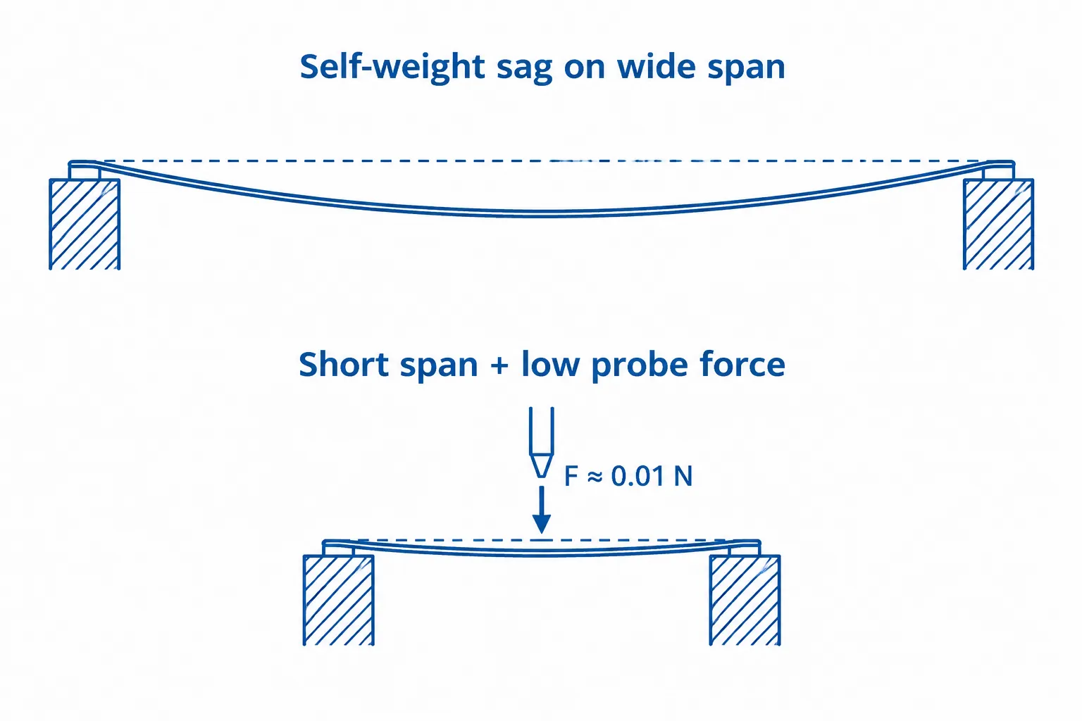
A horizontally supported ejector pin still deflects under gravity; the amount depends strongly on diameter and unsupported span. Moving the supports, adding intermediate support, or changing the head orientation changes the measured curve even though the workpiece has not changed. A contact probe also applies force—on a very thin pin, excessive measuring force can bend the part during inspection and create a false high or low point. A credible measurement plan defines:
- the support or locating datum and free span;
- whether the head is included in the datum or allowed to overhang;
- low and repeatable probe force;
- approved axial measuring positions;
- rotational orientation and sampling density;
- compensation or correlation for repeatable elastic deflection;
- the relationship between the machine reading and the customer’s final gauge.
The goal is not to claim that gravity has been eliminated. The goal is to make its effect controlled, repeatable, and small enough for the agreed acceptance decision.
Straightness, Runout, and Concentricity Are Not Interchangeable
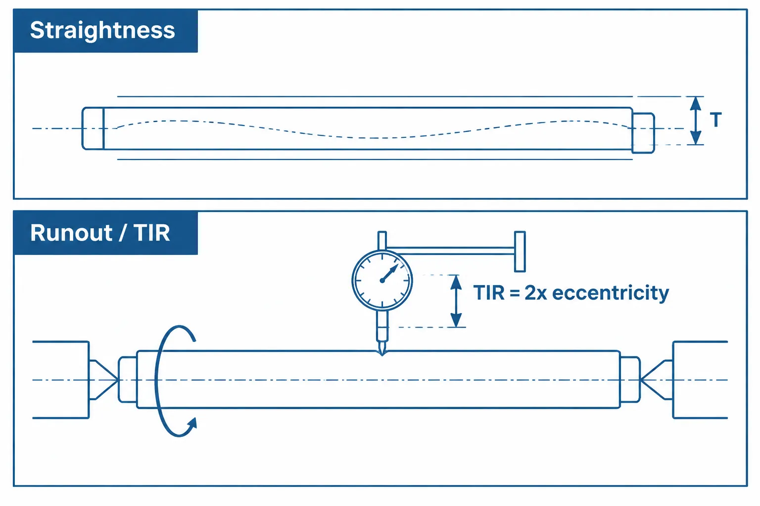
| Characteristic | Meaning | Project Definition Needed |
|---|---|---|
| Straightness | Deviation of a line or surface element from an ideal straight line | Controlled length and evaluation method |
| Radial runout | Surface variation during rotation about a datum axis | Datum, probe position, angular sampling |
| Total indicated runout | Full indicator variation over the measured rotation/zone | Same setup and filtering used by final inspection |
| Concentricity | Relationship between derived axes or centres | Drawing definition and a capable measurement method |
Because straightness, radial runout, and TIR are not interchangeable, the commercial acceptance criterion is only the characteristic named on the drawing and reproduced by an agreed gauge. The 0.02 mm trial target above is a straightness value for the 149 x 5.24 mm family—not a universal runout or concentricity promise.
Recommended Closed-Loop Straightening Process
- Identify and load the correct variant — the operator or handling system loads the pin without dropping, scratching, or bending it. Variant identification selects the approved supports, measuring positions, press limits, and recipe; automatic feeding is added only after real parts pass separation and orientation trials.
- Establish the inspection datum — the pin is located by approved shaft zones, centres, a head/shoulder reference, or dedicated fixtures. Supports must not clamp the part into an artificially straight condition; for small diameters the free span is minimized or explicitly included in the measurement model.
- Measure with controlled force — the pin rotates or indexes while a low-force sensor collects readings at defined positions; the system records the incoming curve and separates repeatable head, groove, or surface signals from centreline bend.
- Select support span and correction point — the drawing and tooling design exclude the head transition, finished tip, vent features, and any surface where contact is prohibited.
- Apply a limited point correction — the press applies controlled displacement or force. Small-diameter, hardened, and coated pins require staged correction with maximum force, stroke, and iteration limits; a single heavy press is never a generic strategy.
- Remeasure using the same setup — after each correction the part is measured again without changing the datum or support logic; another correction is permitted only when the residual error remains outside the validated process window.
- Verify surface and geometry — the final machine result is compared with the drawing-specific rule. Surface inspection, crack inspection, or functional fit checks are included when required by the material, coating, and customer quality plan; accepted and rejected parts can be separated automatically when that function is part of the ordered configuration.
Surface Protection and Correction Risk
Nitrided, through-hardened, HSS, and coated ejector pins do not share one correction window. Tooling must be selected from the real surface and permitted contact zones:
| Risk | Control |
|---|---|
| Support or punch mark | Match tool radius/profile, limit contact pressure, inspect the agreed surface |
| Crack after correction | Limit incoming bend, stage correction, add the required crack-inspection method |
| Coating damage | Use approved contact materials, validate on coated production-equivalent samples |
| False reading from a head or groove | Measure only approved zones or use a validated profile-specific method |
| Elastic deflection mistaken for bend | Control free span, probe force, orientation; correlate with the final gauge |
| Part leaves the fixture during rotation | Validate chuck/centre force without deforming or marking the pin |
“No damage” is an acceptance requirement demonstrated by inspection, not a generic property that can be promised from a machine video.
Point Straightening or Roll Straightening?
| Condition | Point Correction May Be Preferred When | Roll Straightening May Be Evaluated When |
|---|---|---|
| Bend distribution | Local bend locations can be measured and corrected individually | The workpiece has distributed curvature suited to continuous correction |
| Surface/contact | Defined support and punch zones are acceptable | Continuous roller contact is permitted by the surface specification |
| Geometry | Head and steps can be cleared by dedicated fixtures | The usable shaft is sufficiently uniform for the roller arrangement |
| Validation | Closed-loop measurement and correction limits are required | Process trials show acceptable geometry and surface condition |
The final decision follows sample results, not the assumption that all roller contact damages nitriding or that point pressing is always safer.
Sample Test and Acceptance Plan
Representative samples: the smallest-diameter and longest-unsupported-span variant; each material, hardness, and surface-treatment condition; different head, shoulder, and tip geometries; samples across the expected incoming-bend range; more than one production batch where springback may vary; and enough parts to evaluate repeatability rather than one successful correction. Required evidence:
| Record | Acceptance Evidence |
|---|---|
| Part identity | Drawing revision, variant, material, heat treatment, batch |
| Incoming geometry | Agreed datum, support span, probe force, positions, values |
| Tooling | Supports, locator, punch, prohibited contact zones |
| Correction history | Position, force/displacement, iteration count |
| Final geometry | Same measurement setup plus customer-gauge correlation |
| Surface condition | Visual/magnified inspection to the agreed criterion |
| Crack inspection | Method and acceptance rule when required |
| Cycle observation | Measured cycle for the validated configuration |
Automation and Changeover Scope
| Level | Typical Scope |
|---|---|
| Manual loading | Operator loads; machine measures, corrects, verifies |
| Magazine or tray feeding | Controlled presentation for a stable pin family |
| Automatic cell | Feeding, orientation check, correction, result separation |
| Traceable cell | Part/lot identity, recipe, measurement/correction records |
Different diameters and lengths may require physical tooling changes, not only a software recipe. The proposal must define the validated family, changeover method, and checks that prevent the wrong tool/recipe combination.
What Is Not a Universal Promise
Without drawing review and sample validation, this solution does not promise:
- 0.05 mm straightness, runout, or concentricity for every ejector pin;
- one cycle time or yield percentage;
- zero breakage, zero marks, or zero coating damage;
- perfect agreement with an unspecified concentricity tester;
- complete elimination of self-weight deflection;
- one machine range from 1.5 mm to 6 mm or beyond;
- automatic feeding, traceability, or line integration unless ordered.
Related Applications
The wider mold and die workpiece family—ejector sleeves, punch pins, core pins, guide pillars, dowel pins—each needs its own low-force measurement and surface-protection study, but shares this machine platform. Related slender workpieces handled by the same automatic family include steel shafts and bars and small motor worm shafts; medical drill bits have their own dedicated straightening machine line.
Information to Send for a Proposal
Send the drawing and revision, representative samples, diameter/length/head range, material, heat treatment, surface/coating, incoming bend distribution, final characteristic and datum, inspection setup, allowed contact zones, surface/crack requirements, output target, and preferred loading method. Contact us for a sample-based ejector pin straightening study—the proposal will define the support and measurement model, tooling, correction limits, automation scope, and acceptance evidence for the actual pin family.
Frequently Asked Questions
Does a horizontal layout eliminate gravity error?
No. A slender pin supported horizontally still sags. The solution controls the free span, support positions, probe force, and orientation, then correlates the machine reading with the agreed final gauge.
Can nitrided ejector pins be straightened without surface damage?
Potentially, but only after tooling and correction limits are validated on production-equivalent samples. The surface requirement, inspection method, and acceptable contact zones must be defined before a guarantee is made.
Is 0.05 mm straightness the same as 0.05 mm runout?
No. Straightness does not automatically use a rotation datum; runout does. The drawing, datum, measuring position, and evaluation method must identify the required characteristic.
Can one recipe cover several diameters and lengths?
Only within a validated family. Supports, locator, probe position, and punch may require physical changeover; software selection cannot compensate for unsuitable tooling or excessive free span.
What evidence is needed before production approval?
At minimum: drawing revision, representative sample set, incoming/final measurements, machine-to-customer-gauge correlation, correction history, surface inspection, and a repeatability/capability study appropriate to the customer’s quality plan.