
Piston rods and hydraulic cylinder rods are long precision components that push force through seals, bearings and guide elements while reciprocating. Straightness, diameter, roundness and surface condition all feed into assembly behavior, sealing, wear and smooth motion.
A piston rod straightening solution does more than force a bar into a visually straight shape. It defines where straightening sits in the manufacturing route, how the long rod is supported without sag or surface damage, how the controlled characteristic is measured, and how the released rod is accepted against the customer’s reference gauge.
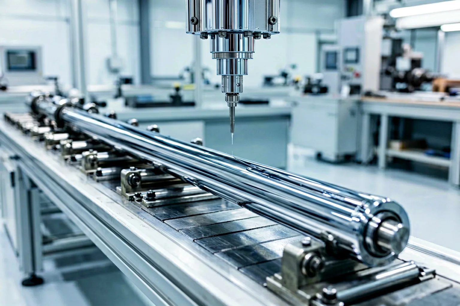
Engineering concept illustration — not a customer-site photograph. Machine length, support spacing, measurement technology and correction method all depend on the drawing and sample tests.
Why Piston Rods Need Their Own Process
Most piston rods look like uniform round bars, but their process risks have little in common with ordinary stock straightening.
| Piston Rod Condition | Straightening Risk | Required Decision |
|---|---|---|
| Long, slender geometry | Self-weight sag can dominate the reading | Define support spacing, orientation and sag-control method |
| Ground surface | Point contact dents, scratches or polish-marks the track | Approve contact material, width, pressure and cleanliness |
| Hard chrome or other coating | Bending or contact can damage the functional surface | Decide whether post-coating correction is allowed, and how it is inspected |
| Induction-hardened zone | Reduced ductility; local response variation | Validate force/stroke limits and crack risk on samples |
| Threaded or machined ends | The end feature may be an invalid support or press zone | Protect the feature and define axial location |
| Multiple diameters or shoulders | Stiffness and measurement tracks change along the part | Map support, measurement and prohibited zones by recipe |
| Hollow or gun-drilled rod | Collapse and ovalization risk differ from solid bar | Validate distributed contact and section limits |
| Final seal-running surface | Cosmetic damage is a functional defect | Include surface acceptance, not only straightness |
The rod may be straightened as peeled stock, after heat treatment, after rough machining, before grinding, or at another approved stage. A process that is safe before finishing may be unacceptable on a finished chrome-plated rod.
Freeze the Manufacturing Stage
The first project question is never “how much machine force is required?” It is “what condition is the rod in when it reaches straightening?”
Before Grinding or Plating
Straightening ahead of the final surface process secures machining allowance and keeps risk away from the finished seal-running track. The catch: later grinding, polishing, heat treatment or plating can move the geometry again, so the plan must leave allowance and include downstream verification.
After Grinding
The rod now carries a precision diameter and surface. Supports, probes and correction tooling must protect it, and the customer must define whether light cosmetic contact is permitted and which inspection method controls acceptance.
After Hard Chrome or Other Coating
Post-coating correction requires specific approval. Coating-substrate system, bend severity, contact pressure, correction strain and inspection method all need validation — no machine can guarantee “zero coating damage” from geometry alone.
Repair or Service Rods
Used rods may hide wear, corrosion, impact damage, local material change or unknown history. Production recipes for new rods do not transfer automatically to repair parts.
Define the Measurement Characteristic
Drawings specify straightness, runout, diameter, roundness, surface finish or customer-specific inspection rules — and these characteristics answer different questions.
- Straightness judges the form of a line or axis under the applicable drawing definition.
- Runout depends on rotation about a specified datum axis.
- A two-support indicator reading depends on support position, rod sag, surface form and station.
- Seal-surface quality is not proven by any straightness value.
Before freezing a generic “TIR” requirement, make sure everyone agrees which of those definitions the number actually represents.
The quotation and acceptance plan should identify:
- the exact controlled characteristic and drawing revision;
- reference features or datum realization;
- measurement stations and usable tracks;
- free-state or supported-state condition;
- support span, rotation method and axial stop;
- filtering, rounding and the decision rule;
- surface inspection and coating requirements;
- the customer reference gauge used for correlation.
Long-Rod Sag and Support Planning
Self-weight deflection grows with rod length, shrinks with section stiffness, and changes with support span. A long rod can show a large probe value even when the material carries no permanent bend of the same shape.
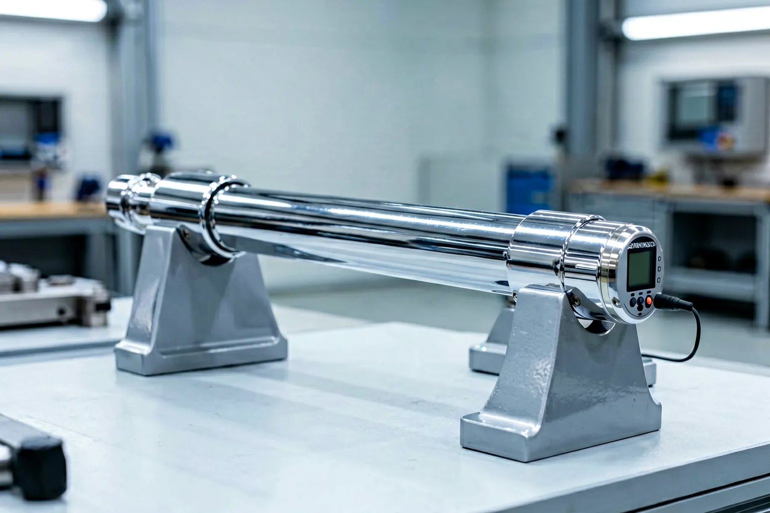
Engineering concept illustration of a polished rod on broad protected rollers. The final number and position of supports and sensors must come from the workpiece range.
| Support Variable | Why It Matters | Control |
|---|---|---|
| Number of supports | Too few allows sag; too many over-constrains the rod | Validate the minimum controlled support set |
| Support span | Changes deflection and the measured shape | Store positions in the recipe; verify at changeover |
| Roller/saddle height | Height error creates apparent bend | Calibrate and inspect for wear |
| Contact width | Narrow contact raises pressure and marking risk | Use validated broad or conforming contact where appropriate |
| Contact material | Drives friction, contamination and surface marks | Approve replaceable sleeves/pads and cleaning rules |
| Probe force | Can deflect a slender rod | Select a suitable contact force or a non-contact method |
| Rotation drive | Slip, end clamping or misalignment shifts readings | Validate drive surface and seating detection |
| Temperature and cleanliness | Affect size, seating and surface condition | Freeze part condition for acceptance |
Repeatability alone proves nothing. A fixture can reproduce the same support-induced deflection beautifully. The measurement must also correlate to the intended drawing definition or customer gauge.
Separate Permanent Bend from Measurement Effects
Before any correction is applied, the control should test whether the observed signal is consistent with a correctable bend. Non-bend contributors include:
- rod sag between supports;
- roller height or support alignment error;
- dirt, chips or damaged protective sleeves;
- local roundness or diameter variation;
- a threaded, grooved or damaged measurement track;
- probe force and fixture deflection;
- end-clamping eccentricity;
- temperature difference or residual oil film;
- axial station mismatch between machine and customer gauge.
On long rods it is often worth measuring multiple axial stations, or moving the measurement and correction frame along a controlled support line. One center reading does not describe the entire part.
Press, Continuous or Hybrid Route
The right method follows from rod geometry, surface stage, bend distribution, length range and production requirement.
| Method | Strong Fit | Main Validation Risk |
|---|---|---|
| Localized press straightening | Discrete bend zones, lower volume, feature-rich ends, targeted correction | Contact marks, local strain, springback, neighbouring-station interaction |
| Continuous/roller straightening | Long constant-section rods with distributed curvature and suitable surface condition | Roller marks, end effects, setup, over-processing, coating damage |
| Moving-frame straightening | Long parts where moving the heavy rod is undesirable | Support transition, station correlation, line length |
| Hybrid route | Stock or pre-finish correction plus final targeted control | Clear responsibility and acceptance at each stage |
No method should ever be selected from diameter alone — the decision walks through surface stage, bend shape and volume, in that order.
Protect the Seal-Running Surface
For a finished piston rod, surface protection is a process requirement, not a cosmetic afterthought.
Approved Contact Zones
The drawing should state where supports, drive rollers, probes and the correction shoe may contact. If the whole OD is a functional seal track, then every contact becomes part of the validation plan.
Contact Pressure and Geometry
Broad rollers, contoured shoes or replaceable sleeves distribute load, but their material and geometry must still be tested. A softer contact is not automatically safe if it traps abrasive particles or deforms unpredictably.
Cleanliness
Chrome and ground surfaces can be ruined by one small chip carried through several rotations. Define tooling-cleaning frequency, sleeve inspection, part cleaning and contamination alarms.
Surface Inspection
Specify how scratches, dents, coating cracks, flaking, roughness change and other defects are judged. Visual inspection alone is not enough for every coating and service condition.
Controlled Three-Point Correction
In localized press straightening, two lower supports create the span and an upper tool applies force between them. Support spacing and press position define the bending moment and the affected region.
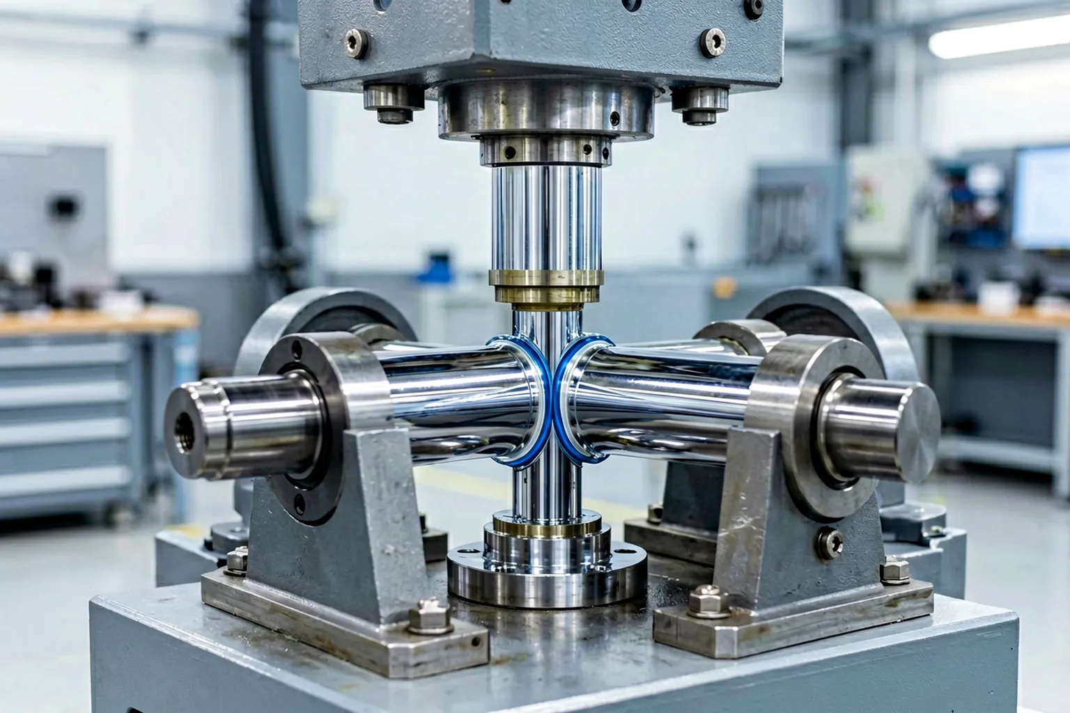
Engineering concept illustration using broad protected contacts. Production tooling and permitted surface pressure must be proven on representative rods.
The correction recipe should define:
- approved support and press tracks;
- support spacing for each diameter/length family;
- press-head width and contact material;
- maximum force, stroke and loaded displacement;
- permitted correction count and reverse correction;
- neighbouring measurement stations to recheck;
- surface inspection after correction;
- conditions that route the part to NOK or manual review.
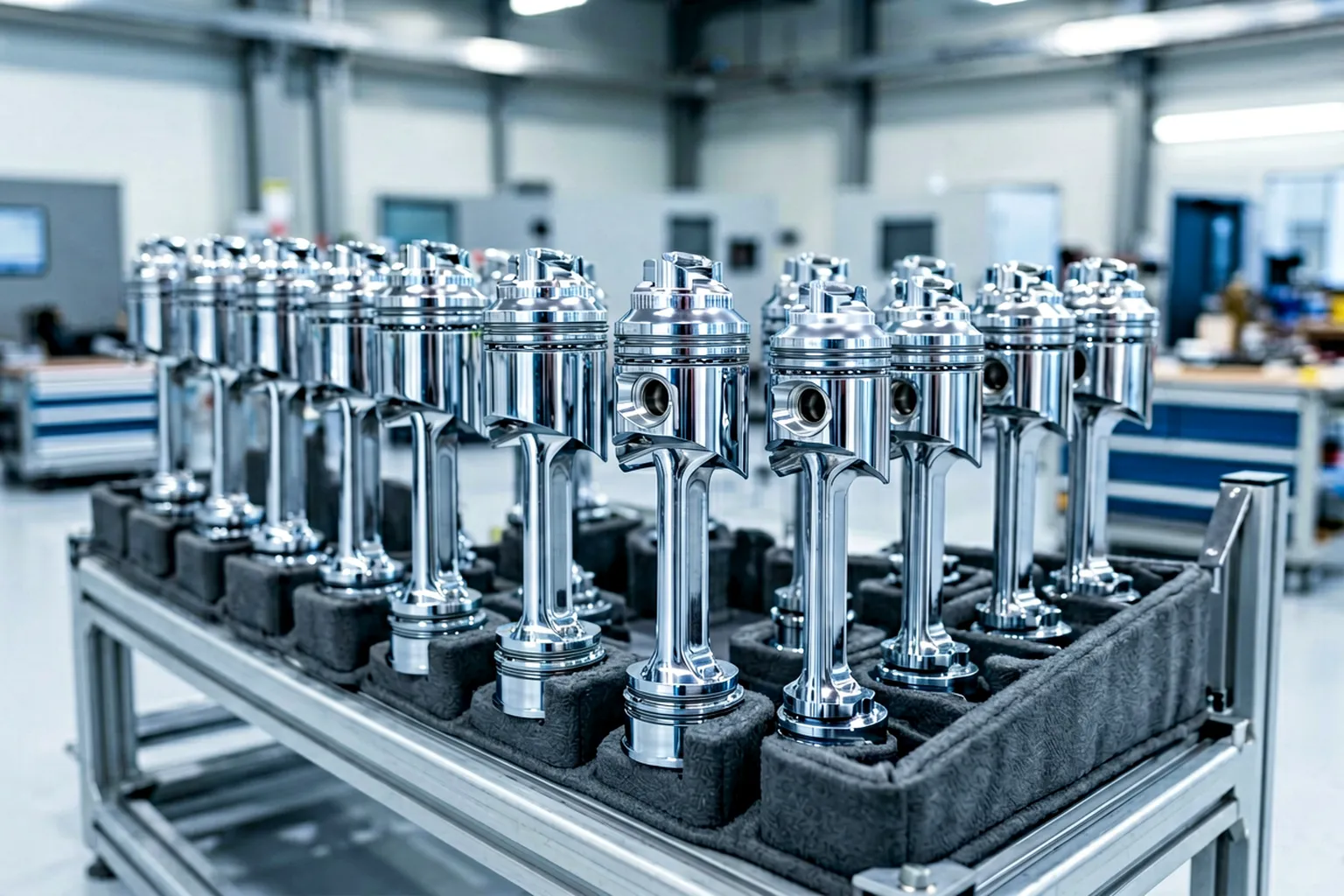
Engineering concept illustration of finished rods staged after correction. The mirrored chrome surface is the functional seal track — its condition is part of acceptance, not an aesthetic bonus.
Springback and Released-Part Acceptance
During a press stroke the rod holds elastic deflection; the final shape exists only after the force is removed. The machine must therefore measure the rod after unloading and after returning it to the defined support and reference condition.
A safe adaptive strategy can refine the next correction from previous released-part response, but it stays inside validated force, stroke and attempt limits — and it stops when readings turn unstable, the part stops responding, the correction direction keeps reversing, or a surface or crack risk appears.
The distinction between loaded displacement, permanent correction and released result is the whole game in springback management; treat any proposal that conflates them with suspicion.
A Defensible Automatic Cycle
- Identify the rod model, process stage and recipe revision.
- Confirm the diameter/length family and the required tooling setup.
- Inspect or clean the rod and the protected contact elements.
- Load and axially locate the rod without damaging threaded or finished ends.
- Verify seating, support positions and measurement signal quality.
- Measure the agreed stations; distinguish sag and form effects from bend.
- Compare the released-part result with correction and acceptance limits.
- Select an approved correction station or continuous-straightening setup.
- Apply controlled correction within force, stroke and contact limits.
- Fully unload, return to the same reference, remeasure.
- Inspect surface and coating per the defined plan.
- Record the result and route the rod to OK, recheck or NOK.
Solid, Hollow and Stepped Piston Rods
| Rod Type | Additional Engineering Question |
|---|---|
| Solid uniform rod | Is curvature distributed or localized — and at which process stage? |
| Hollow/gun-drilled rod | What support/contact pressure avoids ovalization or collapse? |
| Stepped rod | Which diameter establishes the reference, and where may probes and supports contact? |
| Threaded-end rod | How are threads protected and how is axial position controlled? |
| Eye/clevis-end assembly | Can the assembled end rotate, or is another measurement method required? |
| Induction-hardened rod | What hardness and case-depth range — and what crack risk — apply? |
| Chrome-plated finished rod | Is post-plating correction permitted, and what coating inspection controls release? |
Each construction needs its own validated envelope. Never copy a force or stroke from a solid pre-finish bar onto a hollow or fully finished rod — the short, stiff sibling of this family is covered separately in the piston pin straightening solution.
Automation and Data Modules
| Module | Project Definition |
|---|---|
| Infeed/outfeed | Manual, roller conveyor, walking beam, gantry or robot; maximum length and weight |
| Part identification | Model, length/diameter check, wrong-recipe prevention |
| Support line | Number, position, height calibration, automatic setup |
| Measurement | Contact or non-contact method, stations, range, filtering, correlation |
| Correction | Local press, continuous rollers, moving frame or hybrid route |
| Surface protection | Contact material, cleaning, sleeve life, inspection |
| End-feature protection | Threads, eyes, clevises, shoulders, grooves, cross-holes |
| Traceability | Part ID, before/after readings, correction history, final decision |
| NOK handling | Excess bend, unstable reading, no response, overcorrection, surface defect |
| Maintenance | Reference master, calibration, roller/sleeve wear, contamination checks |
Sample Test and Acceptance Matrix
Confirm the machine concept on representative material — never a single easy rod.
| Test Group | Samples to Include | Evidence to Record |
|---|---|---|
| Geometry range | Shortest/longest, smallest/largest section | Support setup, sag, measurement range |
| Process stage | Pre-finish, ground, plated or other approved condition | Contact permission and surface result |
| Bend range | Good, borderline and worst expected incoming parts | Correction response and limits |
| Material/hardness | Full production range | Springback, force/stroke, crack behavior |
| Surface/coating | Representative finish and coating batches | Marks, roughness/coating inspection, cleanliness |
| Construction | Solid, hollow, stepped and end-feature variants | Tooling and protected-zone validation |
| Gauge correlation | Same rods on machine and customer reference | Offset, repeatability, decision agreement |
| Production behavior | Changeover, alarms, NOK, recovery | Recipe control and traceability |
Data Required for a Piston Rod Proposal
Please provide:
- complete drawing and revision;
- rod function and cylinder/application type;
- solid, hollow or stepped construction;
- material, heat treatment, hardness and case-depth range;
- process stage at straightening, including grinding and plating status;
- diameter, total length, straightening span and weight range;
- threads, shoulders, holes, eyes, clevises and other end features;
- drawing characteristic, tolerance, datum and measurement stations;
- customer gauge, support span, filtering and rounding method;
- approved support, probe, drive and correction surfaces;
- prohibited zones and the cosmetic/surface acceptance standard;
- coating type, thickness and permitted post-coating strain/contact rules;
- incoming bend distribution and current reject examples;
- target throughput, loading method and product-family changeover;
- representative good, borderline and NOK samples.
From that input, the support line, measurement method, correction route, surface-protection plan and validation matrix can be engineered. Final accuracy, cycle time and surface result come from the actual rod family and agreed acceptance evidence — not from a generic machine table. Start the conversation through the contact page.
Frequently Asked Questions
Should piston rods be straightened before or after chrome plating?
It depends on the manufacturing route. Pre-plating correction keeps risk away from the finished coating, while later processes can shift geometry again. Post-plating correction requires explicit approval plus coating and surface validation.
Can a roller straightener be used on a chrome-plated rod?
Only after roller geometry, material, contact pressure, cleanliness and coating response have all been validated. A broad contact alone does not prove the chrome surface stays acceptable.
How is sag separated from permanent bend on a long rod?
Through a defined support/reference method, calibrated support positions, suitable measurement stations and customer-gauge correlation. Some projects also need a formal sag assessment or measurement model for the part range.
Is one measurement point at the center enough?
Not necessarily. A long rod can carry several curvature regions or local bends. Station count and placement follow the drawing and the expected deformation pattern.
Can the seal-running surface be used as a support or press zone?
Only with customer approval and representative tests proving the contact creates no unacceptable marks or coating damage. Tool cleanliness and contact-life controls must be defined alongside.
Does the machine check the rod while the press is loaded?
Loaded signals are useful for process control, but final acceptance rests on the fully released rod in the agreed measurement condition.
Can one recipe cover solid and hollow piston rods?
No automatic assumption. Hollow rods can ovalize or collapse and need separate contact-pressure, tooling and sample validation.
What if the machine and the customer gauge disagree?
Investigate support span, datum realization, station position, rod sag, surface/form error, temperature, filtering and rounding. The agreed customer reference and the documented correlation rule decide — not a majority vote.
Related Reading
To explore adjacent workpiece families and straightening processes, see compressor rod straightening, and industrial components straightening.