
A steering knuckle is not a shaft. It is a three-dimensional structural component — cast ductile iron, cast aluminum or forged steel — whose function lives in the relative geometry of several interfaces that never share one rotation axis: the hub bearing bore and hub face, the steering arm with its tie-rod boss, the strut or kingpin interfaces, the brake caliper bosses, and the ball-joint or axle openings. Straightening a knuckle never means “making one axis straight”; it means restoring a defined set of angular and positional relationships between features.
Before any machine or fixture is specified, a workable steering knuckle straightening solution answers five questions:
- Is the knuckle a production part with machining stock remaining, a heat-treated part in process, or a finished part with a damage history?
- Which feature set defines the datum chain — hub bore, hub face, kingpin or strut interfaces — and in what order?
- Is each deviation a global body distortion, an angular tilt of one interface, a bent steering arm, or bore distortion that belongs to sizing rather than straightening?
- Which correction route is approved for the material and heat-treatment state: point pressing, arm correction, controlled sizing, or scrap?
- How will released geometry, crack integrity and post-machining stability be verified before release?
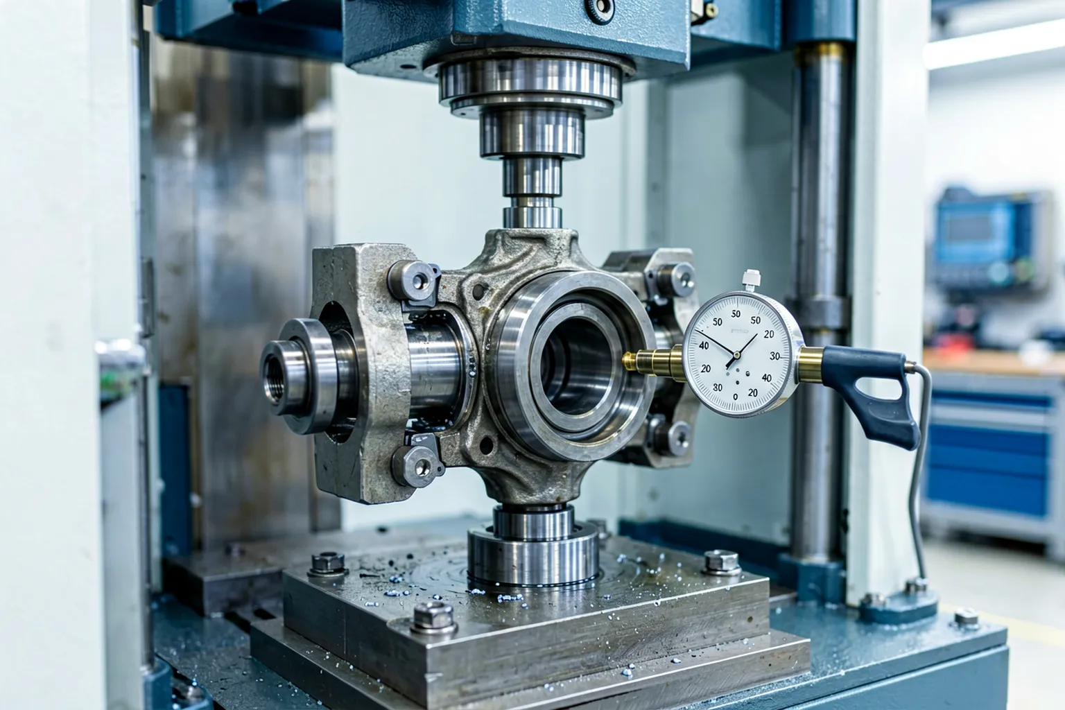
Engineering concept illustration: a knuckle held in a part-specific fixture with a probe monitoring the hub face during a correction study. Not a customer-site photograph. Force positions, datum choices and acceptance limits require the drawing and representative samples.
Two Different Problems Hide Behind One Keyword
Search results for steering knuckle straightening are dominated by collision-repair and enthusiast forums: threads asking whether a car still “drives straight” after knuckle work, debates on unbending a bent knuckle, Facebook repair requests. The one substantive technical page — a collision-industry article on diagnosing bent knuckles from alignment data using SAI, camber and included-angle charts — reaches a blunt conclusion for body shops: cast knuckles are not repairable and should be replaced if damaged.
That doctrine is right for its context — a crash-loaded safety part with unknown internal damage — and irrelevant to another: production and remanufacturing, where distortion is a measured, repeatable process artifact. The two worlds must not share one solution offer:
| Knuckle Situation | Where Distortion Comes From | Engineering Position |
|---|---|---|
| Collision-damaged knuckle on a repaired vehicle | Impact overload, unknown crack history | Replacement, not straightening — a documented safety component |
| Ductile-iron or forged knuckle in production, before or between machining operations | Casting or forging stress relief, machining residual stress, heat treatment | Measurable distortion correction inside a validated process window |
| Die-cast aluminum knuckle (strut type) after machining or heat aging | Ageing stress relief, quench distortion | Limited cold correction; risk assessment per alloy and temper |
| Remanufactured knuckle core | Service wear, prior crash, bearing-failure heat | Full inspection gate: cracks, hardness, dimensions before any correction |
This page addresses the second row and its neighbours: measured distortion control of knuckles inside a manufacturing or remanufacturing process. Nothing here converts a crash-bent knuckle back into a safety-approved part. Neighbouring steering-line workpieces that are routinely corrected in production include the long ball stud; the shaft-family members of the steering line follow shaft-style datum logic instead.
Define the Datum Chain Before Anything Else
Every functional feature must be listed and tied into a datum reference frame on the drawing:
- hub bearing bore — primary axis datum A;
- hub face — secondary planar datum B, controlling brake-rotor runout;
- steering arm geometry — tie-rod boss position and height, controlling linkage angles and toe;
- kingpin bores (solid axle knuckles) or strut fork, pinch-bolt slot and upper mounting face (MacPherson knuckles);
- lower ball-joint opening or press-fit bore;
- brake caliper bracket bosses and abutment faces;
- ABS sensor bore and flange details;
- process datums — locating pads and clamping points used at machining.
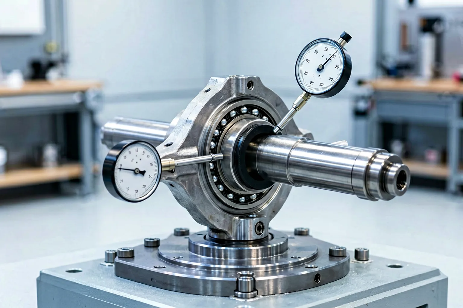
The hub bore normally anchors the frame because the wheel and rotor rotate on it. The collision-diagnostic logic — inferring a bent knuckle from steering-axis-inclination, camber and included-angle deviations — is the assembled-vehicle shadow of the same geometry: a knuckle whose hub bore axis has tilted relative to the strut or ball-joint interfaces appears as an included-angle error that no alignment adjustment can absorb. In production, that deviation is measured directly on the part rather than on the car.
Recognize the Deformation Patterns Separately
Treating “bent knuckle” as one condition produces wrong corrections. Four patterns dominate in practice, each with a different functional consequence and a different route:
| Pattern | Signature | Functional Consequence |
|---|---|---|
| Hub face tilt relative to bore axis | Face runout on the hub face with the bore piloted | Brake-rotor runout, thickness variation, brake judder |
| Angular deviation of hub bore to suspension interfaces | SAI / included-angle type error between datum features | Camber that cannot be aligned out; tire wear |
| Steering arm bend or twist | Tie-rod boss displaced or rotated relative to arm root | Toe and Ackerman errors; arm fatigue under load |
| Bore distortion or boss misalignment | Roundness or position error at press-fit features | Bearing fit and caliper bolt-up problems; belongs to sizing, not bending |
The first two are genuine straightening problems of body geometry. The third is a local arm correction with its own support and load plan. The fourth belongs in a sizing or calibration operation — pressing a bore round while “straightening” risks masking a fit problem that returns after assembly.
Measurement Strategy: Comparative, Then Absolute
Collision diagnostics measure comparatively — against the opposite-side part or an alignment chart — because no drawing data exists in the shop. Production measurement should not inherit that compromise. The correct sequence:
- Pilot the part on the hub bore (or the machining datum bore) in a rotation fixture.
- Probe the hub face for face runout; probe the steering-arm pad and tie-rod boss for position and height.
- Capture the kingpin or strut datum features — bores on a mandrel, or the strut fork on simulated mating surfaces.
- Compare against golden-sample or CMM-mastered values, never against the opposite-hand part.
- Record deviation magnitude and direction for each feature before any correction is attempted.
For low-volume reman work, a granite plate with height gauge and a CMM report per family may suffice. At production volumes the fixture becomes a station on a rotary indexing machine: multipoint electronic probes, a servo press head, and a controller that stores each part’s deviation map before deciding the correction. The pre-correction map is not bureaucracy — without it there is no way to tell a global body distortion from a local arm error, and the wrong feature gets loaded.
Correction Routes and Their Limits
Ductile Iron and Forged Steel Knuckles
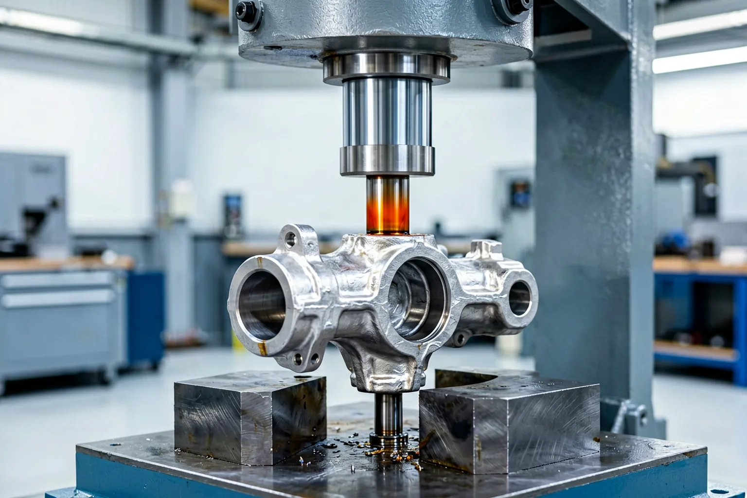
These materials tolerate controlled cold point-pressing once the correction window is validated. The loading plan matters more than press capacity: supports under the rigid boss structure, load applied at or near the feature being corrected, short strokes with springback measured after every stroke. Corrections stay iterative — press, release, re-measure — because castings release stress unevenly and a correction at the arm can shift the hub-face reading. Repeat the full probe map after each cycle, not just the feature that was loaded.
Cast Aluminum Knuckles
Die-cast aluminum knuckles in T6/T7-type tempers have low ductility and a well-earned reputation for cracking under uncontrolled cold bending. Where corrections are approved at all, they are small-angle, low-speed, and validated per alloy and temper on sacrificial samples — frequently followed by a stabilization treatment. Many aluminum knuckle programs simply tighten upstream process control and scrap distortion instead; that decision belongs to the metallurgist, not the machine vendor.
What Point Pressing Cannot Fix
Steering arms that took a bending overload are a fatigue and liability question, not a geometry question. Correcting crash-loaded arms on finished safety parts should be off the table even when the geometry reads straight afterwards — the same replacement doctrine the collision industry applies. Straightening earns its place on process-induced distortion, where the load history is known and the correction window is validated.
Acceptance Gates
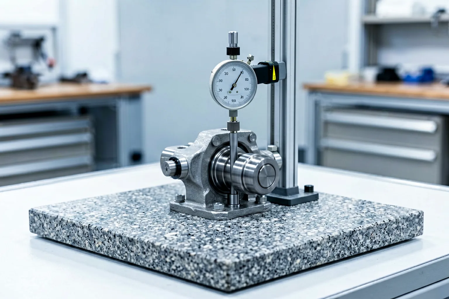
A released straightening process for knuckles holds four gates, in order:
- Pre-gate: crack detection (magnetic particle or equivalent for ferrous parts) before correction — straightening over an existing crack destroys the evidence and the part.
- Geometry gate: a full datum-feature map inside drawing limits — hub-face runout, bore-to-suspension angles, arm position — measured after correction and after any stress-relief or stabilization step.
- Stability gate: re-measurement after the next machining or heating operation; a correction that relaxes back was stress superposition, not correction.
- Traceability gate: each part’s deviation map, correction count and final readings stored against its serial number, with a defined rework limit beyond which the part is scrapped rather than pressed again.
Defining that rework limit honestly — and the NOK sorting rules around it — is what separates a straightening line from a press in a corner.
Common Pitfalls
- Wrong datum order. Correcting to the hub face while the bore is the functional axis produces a part that passes one check and fails assembly.
- One-feature re-measurement. Checking only the corrected feature hides cross-coupled shifts elsewhere on the body.
- Over-pressing castings. Chasing the last fraction of a millimetre with heavy strokes trades visible geometry for invisible microcracks.
- Skipping the stability re-check. Distortion that returns after the next machining operation is the classic signature of unrelieved residual stress — and it appears at the customer, not in your cell.
- No crack gate before correction. A pre-existing crack becomes a field failure with your correction stroke as the documented cause.
Freeze the Process Stage Before Correcting
When the correction happens is as decisive as how. A knuckle measured straight after casting or forging carries stock variation and residual stresses that partially relax during machining; correcting to final geometry at that stage means correcting a body that is about to change. The practical windows:
- After rough machining, before semi-finish: functional datum features exist and stock remains — usually the best window, because the correction supports grinding and boring instead of fighting them.
- After heat treatment or induction hardening of the hub bore: distortion peaks here, and a validated correction recovers parts that would otherwise be scrapped — but the material state limits the window.
- After finish machining: correction is restricted to small angular deviations; every risk of the stability gate applies, and the payoff must justify it.
The stage also decides what “straight” means. Before finish boring, the hub bore is not yet final and the datum must come from the machining datums; after finish boring, the bore itself is the honest reference. A straightening specification that does not name its process point is a specification two departments will interpret differently — which is how parts get correctly corrected at the wrong stage and still fail at assembly.
What a Serious Inquiry Contains
To quote a knuckle straightening station responsibly, a supplier needs: the drawing with datum scheme and tolerance sheet; material and heat-treatment state at the correction point; where the distortion is measured today and with what result distribution; sample parts covering good, borderline and NOK conditions; the required cycle time; and the rework and scrap rules the plant will accept. With those inputs the fixture concept, probe plan and press architecture follow directly — without them, any machine proposal is a guess about which feature actually defines “straight” on your part. Send the package through the contact page to start.
Related Reading
See also: Chassis System Straightening, Automotive Parts Straightening.