
A long ball stud is not a plain round bar, and it is not a complete tie-rod assembly. It combines a slender shank with a highly loaded ball head, a transition radius and — depending on the manufacturing stage — flats, a taper, threads or finished bearing surfaces. The straightening method must correct the usable shank without rolling or pressing on functional zones that were never designed for contact.
A long ball stud straightening solution therefore starts from the drawing and manufacturing route. A roller process may be efficient where the shank is sufficiently uniform and the curvature distributed; measured point correction may be safer when the usable roller-contact length is short or the part carries finished features that demand selective contact.
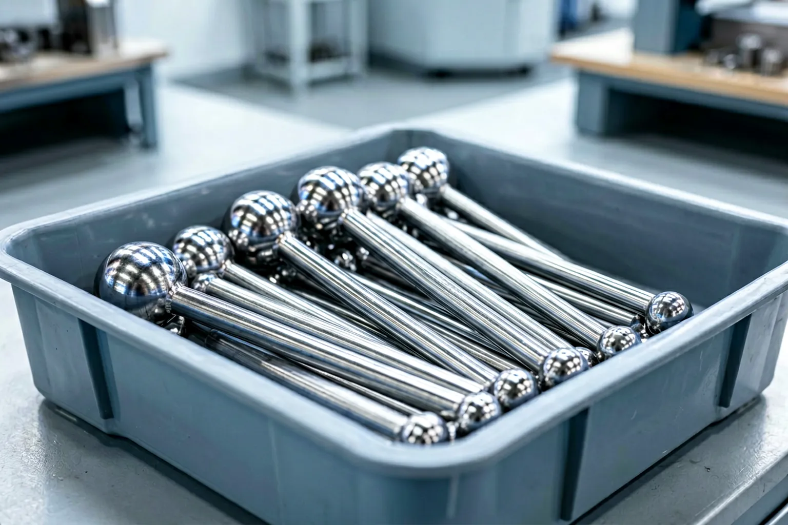
Engineering concept illustration: cold-forged blanks with ball heads and slender shanks, as-processed surface. The image establishes the workpiece type only — not steel grade, hardness, dimensions, final geometry or any customer acceptance.
Ball Stud, Ball Joint and Tie Rod Are Different Products
ZF describes a chassis ball joint as a steel ball stud running in a lubricated bearing cup inside a housing, and a tie rod as a linkage containing inner and outer ball joints connected by an adjusting thread. The workpieces handled by this kind of straightening line are individual long ball stud blanks — not assembled ball joints, and not tie rods.
| Product / Feature | Straightening Implication |
|---|---|
| Cold-forged ball stud blank | Scale and dimensional variation influence feeding, contact and measurement |
| Ball head | Must be guided or cleared without damaging the future bearing surface |
| Head-to-shank transition | High geometric and fatigue significance; normally excluded from concentrated correction |
| Uniform cylindrical shank | Candidate zone for validated continuous roller contact |
| Flat, spline or wrench feature | Changes rotation and can interrupt roller support |
| Taper or thread | Functional assembly zone requiring protected handling and a defined measurement approach |
| Finished / hardened surface | Requires surface-mark, residual-stress and crack controls |
Select the Manufacturing Stage Before the Machine
The same component behaves very differently at each production stage:
| Stage | Typical Reason for Straightening | Main Control |
|---|---|---|
| After cold forging | Remove bend from forming/ejection; prepare for machining | Scale, dimensional spread, generous but defined contact zones |
| After rough machining | Restore geometry before finishing | Protect reference diameters; preserve machining allowance |
| After heat treatment | Correct heat-treatment distortion | Hardness profile, springback, crack risk, limited correction window |
| After grinding / polishing | Meet final geometry | Very strict surface-contact and measurement correlation requirements |
| After coating / plating | Normally an exceptional case | Coating damage, hydrogen-related risk, customer approval |
Required Project Inputs
| Input | Required Detail |
|---|---|
| Drawing | Revision, controlled zones, datums, tolerances, prohibited contact areas |
| Geometry | Ball diameter, shank diameters, length, transition, flats, taper, threads |
| Material | Steel grade, forging condition, relevant mechanical properties |
| Heat treatment | Through/induction/case hardening, hardness profile, treatment sequence |
| Surface | Scale, machining, grinding, shot peening, coating, allowable marks |
| Incoming bend | Magnitude, direction and axial distribution across representative batches |
| Final characteristic | Shank straightness, derived-axis straightness, runout or functional assembly result |
| Production target | Part mix, output, loading, inspection sampling, changeover |
Projects of this type are sometimes quoted around a 20–45 HRC range and a 0.2 mm target. Those remain reported inputs until the actual part condition, characteristic, controlled length and gauge are documented.
Define What “0.2 mm Straightness” Means
| Possible Requirement | Required Definition |
|---|---|
| Shank surface-element straightness | Which surface element and controlled axial length |
| Derived shank-axis straightness | How the axis is constructed from measured sections |
| Radial runout | Rotation datum, probe position, angular sampling |
| Ball-to-shank alignment | Ball-centre construction and shank reference |
| Taper/thread relationship | Datum axis, functional gauge, acceptable variation |
| Maximum gap on a fixture | Support spacing, orientation, gauge method |
A dial indicator on a support fixture, a center-based runout test and a full-profile straightness evaluation do not produce interchangeable results. Machine acceptance must use the drawing-specific characteristic and correlate with the customer’s final gauge.
When Roller Straightening Is a Candidate
Two-roll straighteners are widely used for round bars — manufacturers describe opposed shaped rolls that bend and rotate a bar through a continuous process, and Danieli distinguishes two-roll, multi-roll and other bar-straightening arrangements by application. Those principles support the process family; they do not prove that every ball stud can pass through the same roll set.
A roller process is evaluated when:
- the shank offers enough uniform contact length;
- ball head, transition, flats and end features can be cleared or guided safely;
- the bend is distributed and correctable by the validated roll curve and pressure;
- continuous rotation and contact are permitted by the surface specification;
- the part cannot escape, cock or jam as the head approaches the guide;
- samples demonstrate acceptable geometry, surface and metallurgical condition.
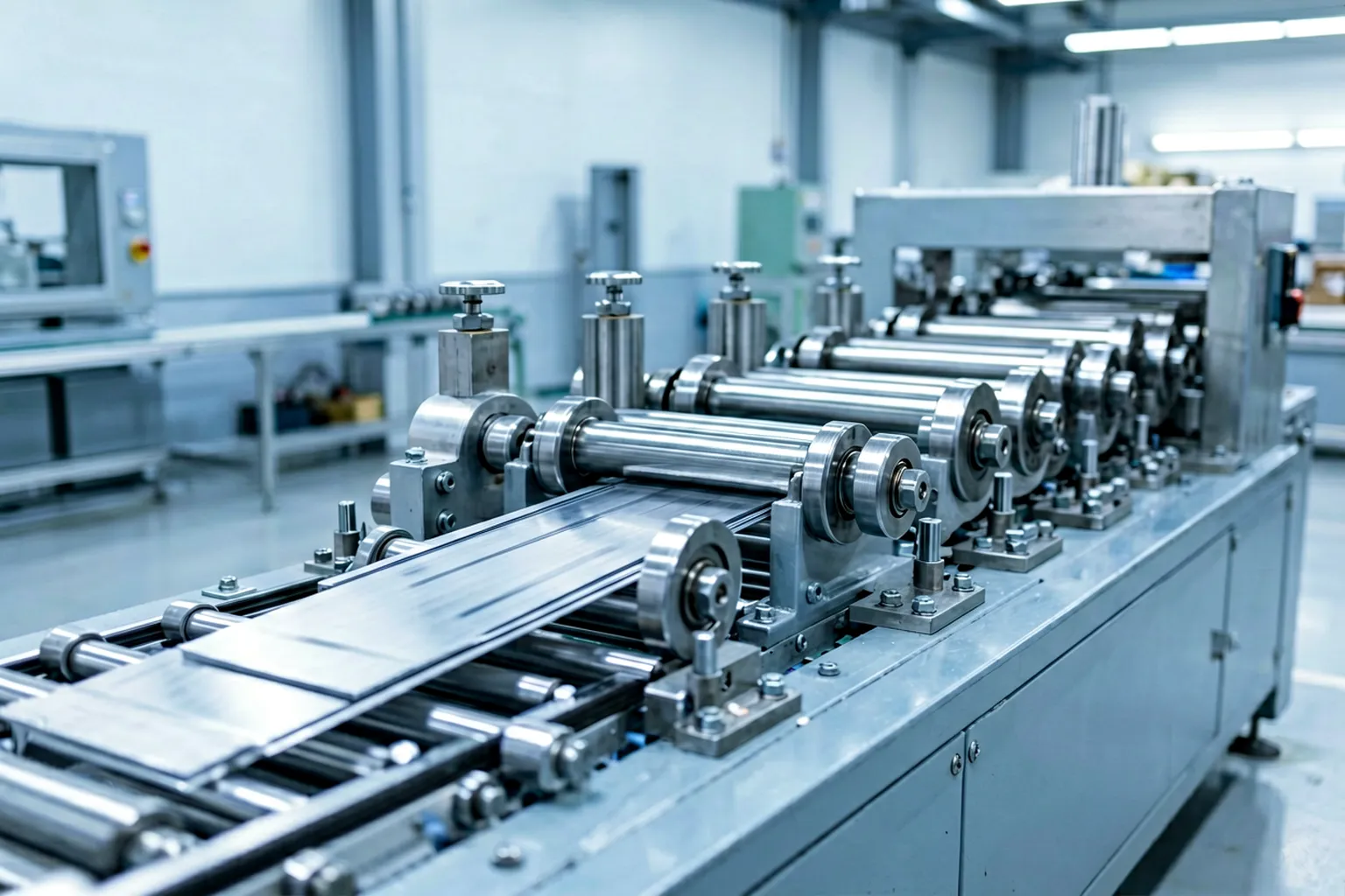
Engineering concept illustration of a roller-type straightening station with guides and a measurement area. It does not prescribe roller count, closed-loop control, speed or accuracy for any specific project.
Recommended Roller Straightening Process
1. Identify the approved variant and stage
The operator selects the recipe for the exact forging, length, shank diameter, hardness condition and surface state. Mixed parts or the wrong manufacturing stage are prevented from entering the roll set.
2. Inspect the incoming blank
Parts with cracks, folds, severe head damage, excessive bend or dimensions outside the validated window are separated before straightening. Straightening is not a repair method for forging defects.
3. Orient and guide the ball head
The entry guide keeps the stud stable while the approved shank zone enters the rolls. The ball head and transition stay outside harmful line contact. Where the part includes flats, their effect on rotation and feeding is validated.
4. Apply the validated roller setting
Roll profile, crossing angle, gap and pressure, guide position and feed speed are recipe-controlled. The setting must create enough plastic correction in the shank without excessive diameter change, polishing, indentation, temperature rise or residual-stress risk.
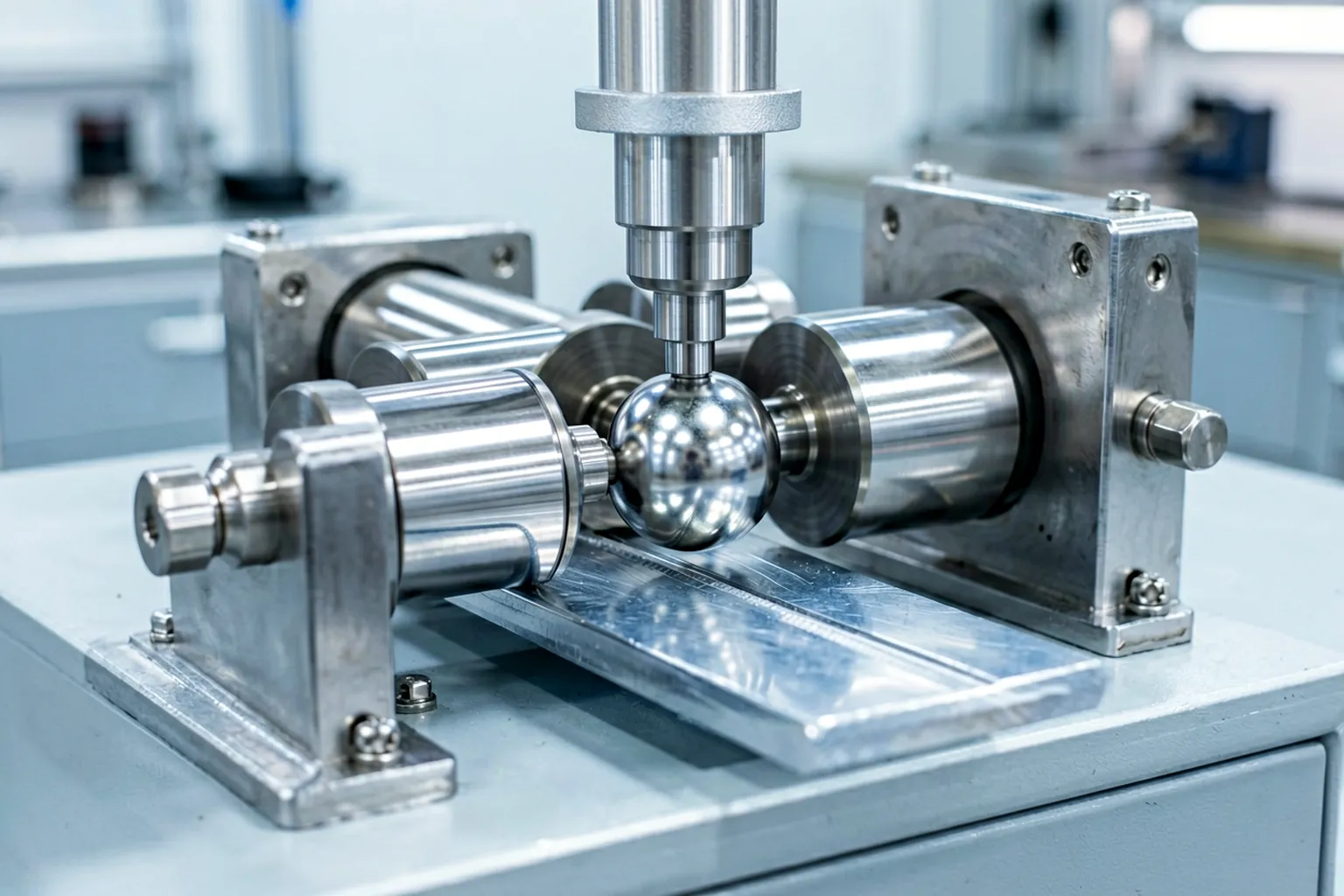
5. Measure using the agreed datum
The part is measured at the specified stations and orientations. Depending on the drawing, this can be an in-machine check, an external gauge, optical profile or rotation-based runout test. The measurement activity belongs to the recipe; automatic final inspection is a scope decision, not a default.
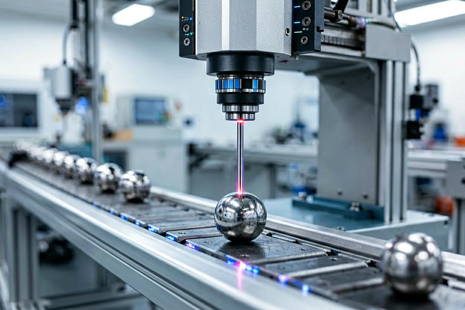
6. Decide pass, reprocess or reject
One additional pass is allowed only where the validated recipe includes it. Unlimited repeated rolling changes surface condition, diameter and residual stress. Parts outside the approved window are quarantined for engineering review.
7. Verify condition as well as geometry
The quality plan can include surface inspection, dimensional checks, magnetic-particle or other crack inspection, hardness verification and downstream machining or assembly trials. Exact methods follow the material, manufacturing stage and customer drawing.
Roller Straightening or Measured Point Correction?
| Decision Factor | Roller Straightening May Be Preferred When | Point Correction May Be Preferred When |
|---|---|---|
| Bend distribution | Curvature is distributed along a uniform shank | One or more localized high points can be measured |
| Contact zone | Continuous shank contact is allowed | Only selected support and press zones are permitted |
| End geometry | Head and other features clear the roll/guide system | Complex ends make continuous passage unsafe |
| Surface | Roller contact and any polishing effect are acceptable | Finished surfaces require localized protected tooling |
| Measurement | Before/after or sampled inspection is sufficient | Closed-loop measurement after each correction is needed |
| Part mix | Stable, higher-volume family | Lower-volume or high-mix parts with dedicated recipes |
Neither method is universally best. A sample study can equally show that straightening should move to an earlier manufacturing stage rather than forcing a finished ball stud through either process.
Head, Transition and Surface Protection
| Risk | Control |
|---|---|
| Ball surface dent or scratch | Clear the ball from working rolls; use approved guides |
| Transition crack | Exclude the radius from concentrated loading; add required crack inspection |
| Shank indentation or diameter change | Match roll profile, pressure and surface condition; measure after processing |
| Flat or thread catches a guide | Define orientation and clearance; use variant-specific tooling |
| Hardened layer damage | Validate contact stress and correction limit on production-equivalent samples |
| Overheating or excessive polishing | Limit speed, pressure and passes; monitor the agreed condition |
| Part exits unpredictably | Positive guides, guarding and safe collection |
Sample Test and Acceptance Plan
Representative samples
- shortest usable roller-contact length and largest head-to-shank ratio;
- minimum and maximum shank diameters;
- every relevant forging and heat-treatment condition;
- each flat, taper, thread and end configuration;
- parts across the real incoming-bend distribution;
- multiple batches where forging scale, hardness or springback can vary.
Required evidence
| Record | Acceptance Evidence |
|---|---|
| Part identity | Drawing revision, variant, material, stage, batch |
| Incoming geometry | Characteristic, datum, positions, values |
| Recipe | Rolls, guides, gap/pressure, angle, speed, pass limit |
| Final geometry | Same defined characteristic plus customer-gauge correlation |
| Dimensions | Shank diameter and functional features remain within tolerance |
| Surface / transition | Approved visual and crack-inspection result |
| Production trial | Measured cycle, jams, changeover, inspection, availability |
The study must include parts near the intended process boundary, not only a few easy samples.
Automation Scope
| Level | Typical Scope |
|---|---|
| Manual | Operator loads, runs the approved pass, unloads for inspection |
| Assisted | Infeed/outfeed support and guided collection |
| Automatic | Separation, orientation, rolling, measurement, result sorting |
| Traceable | Part/lot identity, recipe, measurement and process records |
Automatic loading depends on whether the ball heads tangle, whether flats or tapers require orientation, and whether surface contact is allowed. Automation and traceability are ordered scopes, not assumptions.
What Is Not a Universal Promise
Before drawing review and sample validation, this solution does not promise:
- 0.2 mm straightness for an undefined characteristic;
- one process window for every 20–45 HRC part;
- suitability for assembled ball joints or complete tie rods;
- safe roller contact on finished balls, tapers, threads or coatings;
- one roller setting for all lengths and diameters;
- zero cracks, marks, diameter change or residual-stress effects;
- a fixed cycle time, output increase or cost reduction.
Related Applications
On the steering and chassis side, the steering knuckle straightening solution covers the three-dimensional structural neighbour of this part. If the component has a steering rack or assembled tie-rod function, it requires a separate datum and functional-risk study.
Information to Send for a Proposal
Send the drawing and revision, representative samples, ball/shank/transition dimensions, flats/taper/thread details, material and heat-treatment route, exact manufacturing stage, surface condition, incoming-bend distribution, final characteristic and datum, customer gauge, prohibited contact zones, crack-inspection requirement, output target and preferred loading method — through the contact page. A sample-based study then defines the suitable process stage, roller or point-correction concept, protected zones, measurement method and acceptance evidence for the actual part family.
Frequently Asked Questions
Is a ball stud the same as a tie rod?
No. A ball stud is a component inside a ball joint. A tie rod is a larger steering linkage that normally includes ball joints and an adjusting connection. This solution concerns individual long ball stud blanks or parts.
Can the ball head pass between the straightening rolls?
Not by default. The ball and its transition are functional, highly loaded zones. Tooling normally clears or guides them while the approved uniform shank enters the rolls. Any direct contact requires explicit drawing approval and sample validation.
Can parts hardened to 45 HRC be roller-straightened?
Possibly, for a specific material, hardness profile, geometry and incoming bend — but the number alone is insufficient. Springback, case depth, transition stress, crack risk and permitted surface contact must all be tested.
Is 0.2 mm a straightness or runout requirement?
The number alone cannot answer that. The drawing must name the characteristic, controlled length, datum, measurement positions and evaluation method. The machine and customer gauge then need a correlation study.
When should point correction be considered instead?
When the bend is localized, the usable roller-contact length is short, complex features prevent safe continuous passage, or finished surfaces require selective tooling and closed-loop measurement.
Related Reading
See also: Fastener Straightening.