
A piston pin — wrist pin, gudgeon pin — is the short, close-tolerance cylinder joining the piston to the connecting rod small end, and it is among the most heavily loaded parts in a reciprocating engine. Load reverses every revolution; the outer diameter works as a bearing journal inside the rod bushing, and on full-floating designs the bore is a running surface in its own right. Solid, center-cored or end-drilled, the pin must hold micrometer-level diameter, roundness and straightness simultaneously.
Short and stiff, a pin is not straightened with brute force. It takes very small, precisely placed plastic corrections, delivered under a measurement regime that can tell a true axis bend from roundness error and diameter variation. Five questions come before any machine selection:
- Solid, center-cored or end-drilled — and what length-to-diameter ratio?
- Where does the deviation appear: after grinding, after heat treatment, or after handling?
- Is the radial runout a genuine centerline bend, or roundness and diameter error misread as bend?
- Which correction route is approved for the material and hardness state — precision point pressing, rotary fine-straightening, or scrap?
- How will released geometry, surface integrity and fatigue-critical acceptance be verified after correction?
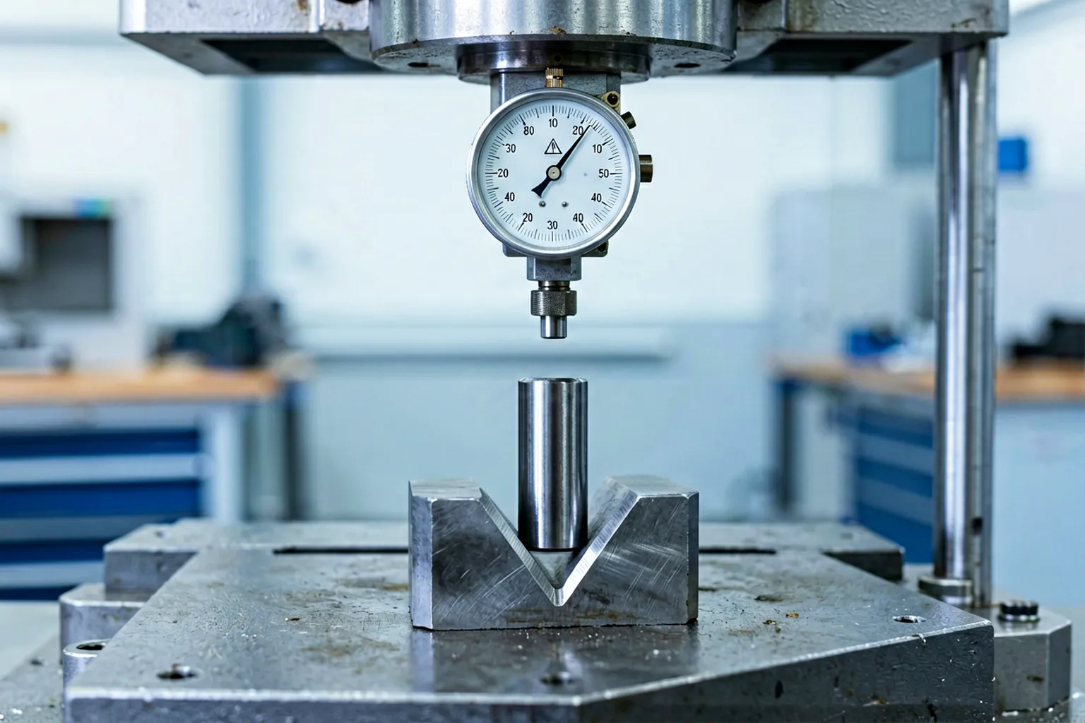
Engineering concept illustration: a hardened piston pin supported and measured during a controlled correction study — not a customer-site photograph. Contact zones, force limits and machine architecture come from the drawing and representative sample tests.
A Piston Pin Is Not a Piston Rod
Public search results for piston pin straightening are dominated by automotive forums — hobbyists freeing stuck pins or asking whether a stiff wrist pin can be reused after a rebuild. That repair conversation shares nothing with the production problem: a pin manufacturer grinding thousands of pins a day who needs a controlled correction step between heat treatment and final grinding. The two intents must never share one machine specification.
Just as important, the pin must not be confused with the piston rod (the long hydraulic-cylinder component with its own solution page) or with the connecting rod (a forged I-beam part, not a precision cylinder). The pin is its own workpiece family with its own constraints:
| Workpiece | Typical Geometry | Straightening Character |
|---|---|---|
| Piston pin (this page) | Short cylinder, L/D ≈ 1.3–2.5, hardened, often cored | Very stiff; small bend values, high correction forces, ovality risk |
| Piston rod (hydraulic) | Long slender rod with threaded ends | Low L/D stiffness; multi-point correction over a long span |
| Connecting rod | Forged I-profile with two bores | 3-D bore-to-bore alignment, not a centerline problem |
| Engine valve | Long stem with head | Stem straightness relative to head face; similar micro-correction logic |
How Piston Pins Deform
Production pins are typically turned or cold-drawn from case-hardening steel, carburized and hardened, then ground. Deviation enters at predictable points:
- Heat-treatment distortion. Carburizing and quenching release turning stresses unevenly; a cored pin bows toward the thinner wall. This is the most common — and most correctable — deviation source.
- Grinding-induced stress. Heavy or one-sided OD stock removal unbalances residual stress, and the pin bows after leaving the grinder.
- Handling and clamping damage. Short, hard and heavy for their size, pins pick up sharp local kinks from a drop onto a bin edge — a damage class that is a scrap decision, not a straightening decision.
- Ovality growth in cored pins. The bore distorts during heat treatment and the OD follows. That is a form error, not a bend, and no press cycle fixes it.
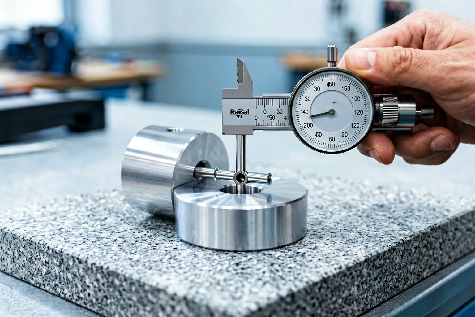
Measurement: The Datum Decision Comes First
A pin straightness check only means something against a defined rotation axis. Two support conventions dominate.
Between Centers
Where the pin carries center holes produced and ground as process datums, measuring between centers reproduces the grinder’s axis — usually the cleanest convention for final acceptance. The holes themselves must be clean and undamaged: a nicked center produces phantom runout and sends good pins to the press.
On V-Blocks or Rotating Supports
For cored pins without centers, the OD becomes the datum. A rotating V-block setup with a dial test indicator or a multi-point electronic measuring head maps runout at several axial stations. The critical discipline here is separating error types: a first-harmonic, once-per-rev component that holds its phase along the length is a bend; a second-harmonic component is ovality. Pressing an oval pin to chase a runout number destroys the part.
Loaded Versus Released
With stiff pins and tiny corrections, gravity and support deflection are not negligible against the tolerance. The measuring condition — supports at fixed stations, indicator at defined planes — must be frozen in the work instruction, and post-press verification must repeat it exactly. The general arguments for released-state acceptance apply with full force at this scale.
Process Routes for Straightening Pins
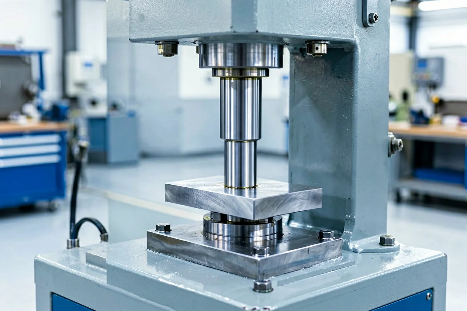
Precision Point Pressing
The default route: the pin rests on two narrow hardened supports placed close to the bend apex, and a small ram applies a controlled stroke — displacement-limited, not force-limited — at the high point. Three features separate pin pressing from ordinary shaft pressing:
- Support spacing. With L/D under about 2.5 the supports sit close together and local contact stress runs high. Support inserts need a relieved or radiused contact that clears the pin OD without brinelling it.
- Stroke resolution. Corrective strokes are measured in micrometers. The press needs sub-micrometer stroke resolution and stiff, backlash-free ram guidance, because the springback-to-stroke ratio on a hardened pin can exceed 10:1 in a bad setup.
- Springback compensation. Hardened pins spring back hard; the process must over-press and relax into tolerance under explicit compensation rules.
Rotary Fine-Straightening
At higher volumes, pins can pass through a small rotary straightening head — angled rolls applying alternating plastic bends in one pass. The route pays off only where pin geometry is uniform along its length (no heads, grooves or abrupt features) and the deviation is a smooth global bow rather than a local kink. Local kinks survive roll straightening and resurface at final inspection.
When Not to Straighten
A pin with a sharp handling kink, visible brinelling, cracks, or ovality outside the drawing is scrap. Fatigue-loaded engine parts do not forgive creative rescue attempts. A written rework limit — how many correction cycles a pin may receive, and at which stage — belongs in the control plan.
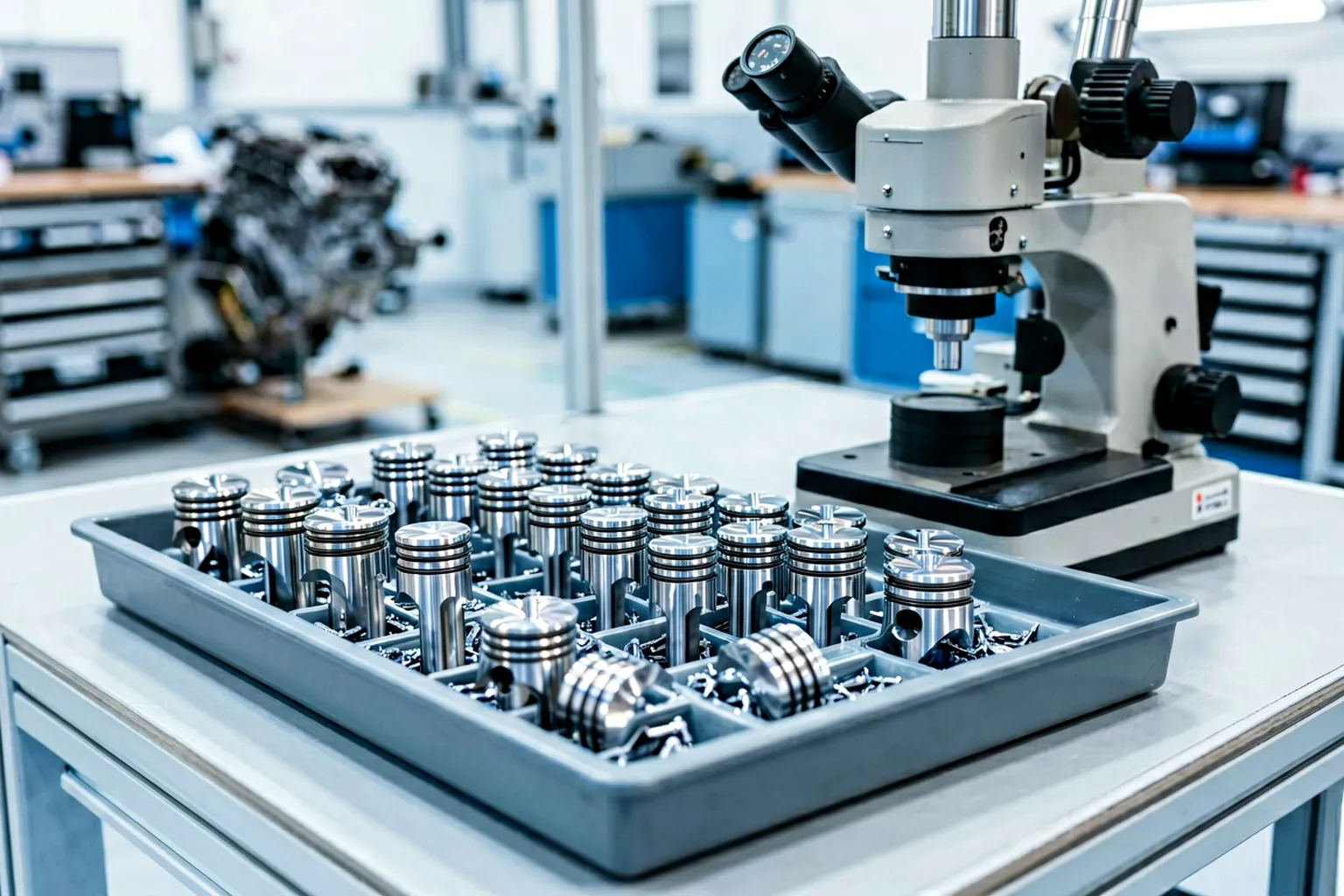
Engineering concept illustration of finished pins staged for verification. Roundness and diameter are re-checked after correction — pressing must never trade bend tolerance for form tolerance.
Why Short, Stiff Parts Are Harder Than They Look
Intuition says short parts should be easy. The opposite holds, and the reason is the triangle of bend amplitude, section stiffness and stroke resolution. A long slender shaft with a 0.5 mm bow is corrected by a stroke of a few tenths of a millimetre — comfortable for any press. A piston pin’s entire out-of-tolerance population may sit between 0.005 mm and 0.020 mm of bow; correcting it takes strokes of a few micrometers on a section whose bending stiffness per unit deflection is an order of magnitude above a slender shaft’s. Three consequences follow:
- Machine resolution becomes the process. A press with 0.01 mm stroke resolution cannot govern a 0.003 mm correction. Ram guidance, load-cell noise, frame thermal growth and oil compressibility all enter the tolerance band. Pin-machine selection starts from stroke resolution and frame stiffness, never tonnage — a pin press needs almost no force, only extreme control.
- The support condition dominates the mechanics. With supports close together under a stiff section, correction happens as much through localized pressure distribution as through global bending. Moving a support 2 mm changes the effective recipe, which is why support positions belong to the recipe record, not to operator discretion.
- Local damage risk is high. High stiffness plus small contact zones equals high contact stress. Every anvil and ram insert must be hardness-matched and radiused; a flat steel anvil against a hardened pin OD is a brinelling machine.
Freeze the Process Stage Before Writing the Recipe
A correction recipe is valid for exactly one material state and one stock condition. Pin production crosses several states, and each defines a different window:
| Stage | Correction Opportunity | Main Risk |
|---|---|---|
| Soft blank, before carburizing | Rarely needed; turning holds geometry | Recipe will not transfer to later states |
| After hardening, before grinding | Bow at its largest; correction restores grinding-stock distribution | Surprise stock loss on one side where bow was masked by stock |
| Between rough and finish grinding | Classic correction point; stock still available | Grinding stress added after correction re-bows the pin |
| After final grinding | Micro-correction only, tightly cycle-limited | Surface evidence on the finished bearing surface; ovality interaction |
| At customer incoming inspection | Dispute territory — re-measure under an agreed convention first | Correcting against an unverified measurement |
The control plan should name the correction stage explicitly and forbid correction anywhere else. A pin corrected after final grinding carries no protective stock: every press mark, every bit of ovality growth, every over-correction cycle is a functional defect on a fatigue-loaded part.
Acceptance Criteria
A pin straightening process is accepted on evidence, not a passing runout number alone:
- Straightness or TIR at the drawing-specified planes and support condition — typically low micrometers for ground pins.
- Roundness and diameter re-checked after correction; pressing must not trade bend tolerance for form tolerance.
- Surface integrity. No press marks, brinells or anvil witness lines on the OD bearing surface. Contact evidence on a functional journal surface is a reject, not a cosmetic note.
- Verification measurement system. The gauge must actually resolve the tolerance — a formal measurement-system study belongs in the acceptance file.
- Process capability tracked over time, with rework counts and scrap reasons recorded per heat-treatment lot.
Common Failure Modes in Pin Straightening Projects
- Chasing ovality with the press. The trace shows twice-per-rev error, the operator presses anyway, and the pin ends up both oval and bent.
- Hardness-state mismatch. A stroke recipe developed on soft pins is applied to hardened pins; springback triples and the window disappears. Bind every recipe to a material state.
- Over-correction cycles. Back-and-forth pressing at one apex works the material and, on a fatigue part, is a latent failure risk. Cycle limits must live in the machine control, not in operator memory.
- Damaged datums. Tumbled or dirty center holes, or V-blocks with embedded swarf, generate false bend maps and trigger correction of straight pins.
- Measuring in a different condition than the customer. Your inspection shows straight; the customer measures between clean centers on a different span and sees runout. Align the measurement conventions contractually.
For a pin-family feasibility study, prepare drawings, the heat-treatment state, current runout data from at least 50 parts, and the acceptance specification to be met after correction — then send them through the contact page. The sister solution pages for piston rods, engine valves and connecting rods cover the neighbouring workpieces on the same engine assembly.