
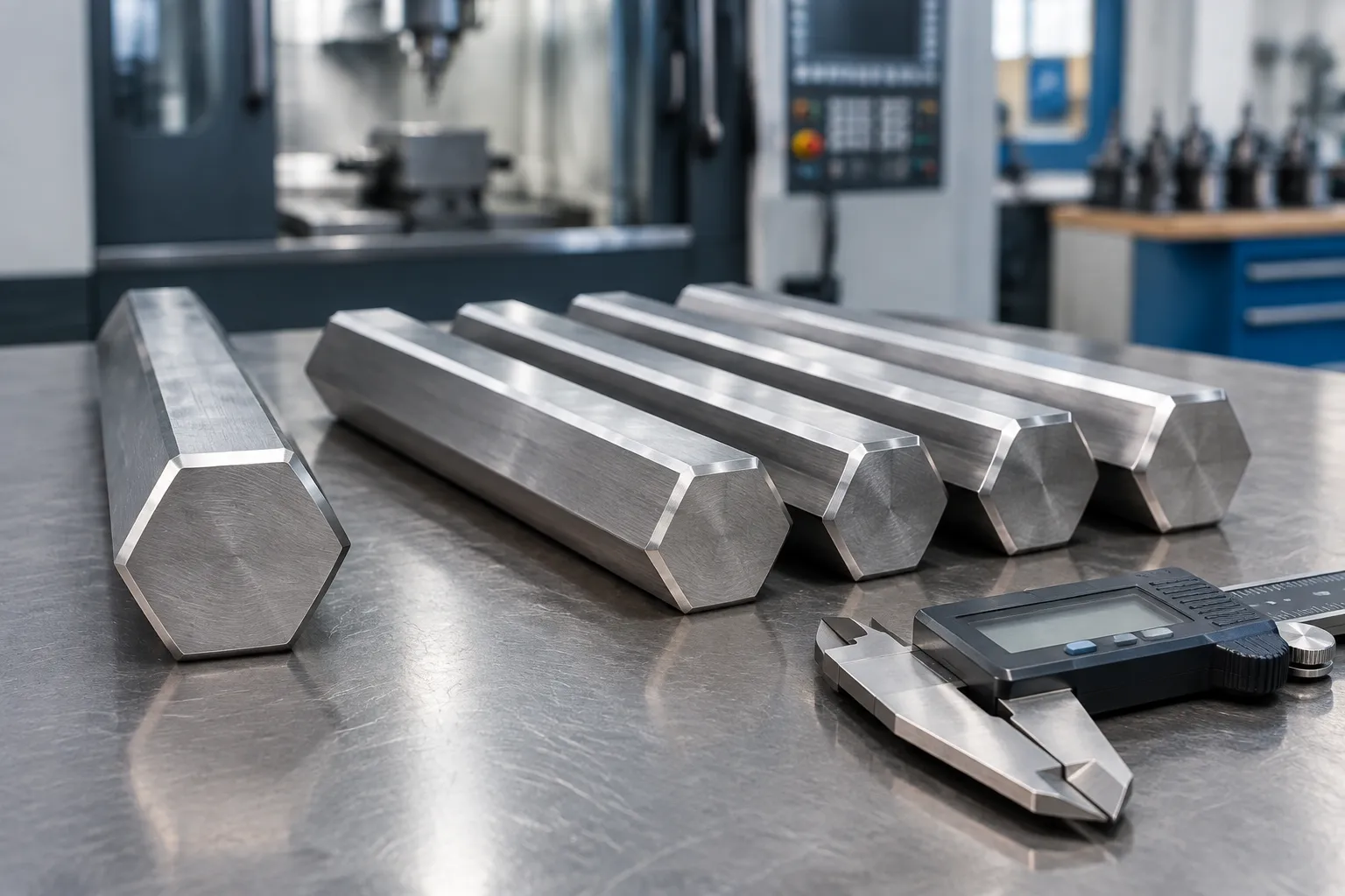
Small hexagonal pins combine the handling difficulty of a slender part with the measurement difficulty of a non-round profile. Depending on its angular position, a pin presents a face, a corner or a stepped end to the camera. Unless inspection datum and orientation are controlled, a change in silhouette gets mistaken for bend. The straightening cell must therefore coordinate feeding, orientation, optical screening, measured correction and final verification.
For high-volume production, the most effective architecture is often not to straighten every pin. A fast inspection stream lets conforming pins bypass correction entirely, while only the measured bent population enters a slower closed-loop straightening branch.
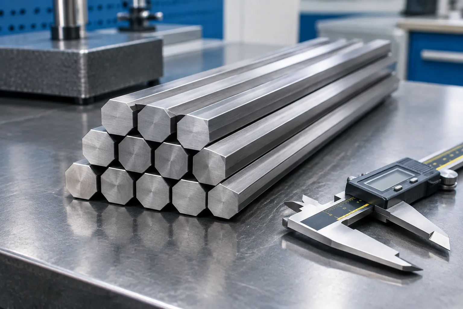
Engineering concept illustration: slender, dark-finished pin-type workpieces with non-round bodies and differing visible end lengths. The image supports the workpiece family; it is not a dimensional inspection record.
Start With the Correct Hexagonal-Pin Definition
| Drawing Feature | Why It Matters to the Cell |
|---|---|
| Across-flats dimension | Selects nest, guide and approved face-contact tooling |
| Across-corners dimension | Determines clearance and optical silhouette extremes |
| Round or reduced end diameter | May provide orientation, assembly or locating information |
| Overall and controlled length | Defines support span and optical field/scan positions |
| Face/edge straightness | Determines which profile element is evaluated |
| End-to-body relationship | Determines whether orientation and alignment must be verified |
| Material, hardness, surface | Sets correction and contact-mark limits |
Projects of this type are sometimes described as “1.5 mm and 1.9 mm diameters.” For a hexagonal body that is incomplete: the drawing must state whether those numbers are across flats, across corners, or the diameter of a round end. A reported 80 mm length is likewise a project input until the drawing confirms it.
Separate the Screening Stream From the Straightening Stream
One representative project reported 80,000 pins to be screened in three hours, with roughly 500 bent pins allowed eight hours for correction. Those are two different process streams:
| Stream | Reported Input | Engineering Interpretation |
|---|---|---|
| Optical screening and bypass | 80,000 parts / 3 h | ≈7.4 parts/s gross; parallelism, continuous motion or multiple inspection positions must be studied |
| Bent-part straightening | 500 parts / 8 h | ≈62.5 parts/h — close to one corrected part per minute before allowances |
| Reported machine statement | 2 parts/min | Unverified; dependent on correction iterations and handling |
The arithmetic is useful for architecture, not proof of achieved throughput. Availability, refill time, jams, false rejects, recipe change, correction iterations and final verification all belong in a real capacity study.
Required Project Inputs
| Input | Required Detail |
|---|---|
| Drawing | Revision, across-flats/across-corners sizes, end geometry, datum, tolerance |
| Material condition | Grade, hardness, heat treatment, coating, acceptable contact marks |
| Part population | Straight/bent ratio by batch; incoming bend distribution |
| Measurement characteristic | Straightness, profile, axis location, runout or functional insertion result |
| Optical setup | Lighting, background, magnification, field of view, orientations, edge algorithm |
| Part presentation | Bulk condition, oil, burrs, static, tangling, mixed variants |
| End orientation | Required head/tip direction; handling of ambiguous parts |
| Production target | Screening, correction, verification and reject-stream rates, separately |
| Traceability | Lot, recipe, measurement result, correction record requirements |
Why Angular Orientation Changes the Measurement
A round pin can be rotated while a probe tracks a nominally constant-radius surface. A hexagonal pin presents six faces and six corners: optical width and edge position change as the part rotates even when its centerline is perfectly straight.
The measurement plan must commit to one of the following:
- index a known face to the camera and evaluate a specified pair of edges;
- capture multiple controlled orientations and reconstruct the centerline;
- use a calibrated profile model separating the nominal hexagon from bend;
- measure a round reference section where the drawing makes it the functional datum.
ISO 1101 provides the language for geometrical tolerancing; the drawing must still identify the actual toleranced feature. Optical systems can measure straightness and profiles without contact, but the program, fixturing, lighting and edge-detection capability must be validated for this specific part.
The Two-Stream Process, Step by Step
1. Separate and present one pin
A bowl feeder, tray or other presentation system separates one pin at a time without scratching or wedging the slender parts. Successful feeding across all production conditions still requires a representative run-off test with the real batch state.

2. Verify variant and end orientation
Sensors or vision distinguish the approved part family and identify the required head/tip direction. A part that is ambiguous, overlapped or outside the image limits is rejected or re-presented — the controller does not guess.
3. Perform fast optical screening
The part is held in the validated orientation and inspected against the drawing-specific profile rule. Conforming pins proceed directly to the bypass output; suspect pins enter the straightening branch. False-pass and false-reject rates must be established with known reference parts and a gauge correlation study.

4. Locate the pin for correction
Dedicated supports contact approved faces or body zones. The tooling prevents angular roll and leaves the correction zone accessible. Stepped or reduced ends are protected from gripping and point load unless the drawing permits contact.
5. Apply controlled point correction
The press corrects one measured bending plane using limited displacement or force. For a hexagonal section, the recipe links support face, press direction and optical orientation. Where bend exists in more than one plane, the pin is indexed to another validated orientation rather than pressed from an arbitrary angle.

6. Remeasure and decide
The pin returns to the same optical datum. Another correction is allowed only within the validated limits for iterations, displacement/force and remaining bend. Accepted, retry and reject states stay separate.
7. Transfer the accepted pin in the required direction
The cell can hand an accepted pin to a tray, conveyor, robot or downstream insertion process. The external interface and cycle synchronization are project options, not standard equipment.
Measurement and Handling Risks
| Risk | Control |
|---|---|
| Face/corner silhouette mistaken for bend | Index orientation; use a validated profile/centerline algorithm |
| Contact probe deforms a small pin | Prefer suitable non-contact inspection or validate low probe force |
| Pin rolls during correction | Profile-matched anti-rotation support |
| Surface or edge marking | Define permitted contact faces, radii, material and pressure limits |
| Mixed thick/thin-end direction | Positive orientation detection; reject ambiguous images |
| Bowl feeder tangling or double feed | Test real batch condition; detect overlap at transfer |
| Over-correction | Limit each correction; remeasure before another iteration |
| Straight pin sent to the slow loop | Validate the optical decision threshold and gauge correlation |
Define the 0.03 mm Requirement Before Quoting It
Project pages sometimes present 0.03 mm as achieved accuracy without naming the characteristic or measurement setup. It could refer to one profile edge, a derived centerline, radial variation, maximum gap or a functional insertion result — and those are not interchangeable.
Before any guarantee, define:
- the toleranced feature and controlled length;
- datum and angular orientation;
- whether the value is straightness, profile, runout or another characteristic;
- optical calibration, resolution and edge rule;
- machine-to-customer-gauge correlation;
- repeatability/reproducibility and process-capability method;
- treatment of burrs, surface texture and tapered or rounded ends.
Sample Test and Acceptance Plan
| Test Group | Evidence Required |
|---|---|
| Reference straight parts | Optical pass decision and customer-gauge agreement |
| Known bent parts | Detection across bend directions and magnitudes |
| Size variants | Correct nest, recipe, optical scale, orientation |
| Surface/batch variants | Stable lighting, feeding, contact condition |
| Boundary parts | False-pass/false-reject behavior near the decision limit |
| Corrected parts | Before/after geometry, correction history, condition inspection |
| Extended run | Availability, jams, refill, decision distribution, actual throughput |
The run-off must include both streams. A cell can meet the correction rate yet fail the overall target because the feeder, the optical decision or the bypass transfer is unstable.
What Is Not a Universal Promise
Without the drawing, representative samples and an acceptance study, this solution does not promise:
- 0.03 mm for an undefined characteristic;
- 80,000 screened parts in three hours;
- 500 bent parts corrected in eight hours, or two parts per minute;
- automatic recognition of every thick/thin-end variant;
- one machine covering all nominal sizes without defining the hexagonal dimensions;
- zero scratches, zero jams or zero false decisions;
- a collaborative robot or downstream insertion system as standard.
Related Applications
Neighbouring small-part applications with the same bulk-feeding and auto-orientation logic include the connecting rod sleeve straightener, where asymmetric ends and slender geometry pose the same presentation problems. The hexagonal pin adds its own angular-indexing and optical-decision model on top.
Information to Send for a Proposal
Send the drawing and revision, representative straight and bent samples, across-flats and across-corners dimensions, overall and end geometry, material/hardness/surface condition, incoming bend distribution, geometric characteristic and datum, customer gauge, required end direction, bulk presentation condition, screening and correction rates, downstream interface and traceability needs — through the contact page. A sample-based study then defines the two-stream architecture, optical datum, orientation method, correction tooling, automation scope and acceptance evidence for the actual pin family.
Frequently Asked Questions
Is 1.5 mm the diameter of a hexagonal pin?
Not necessarily. A hexagonal section is normally identified by across-flats and/or across-corners dimensions, and a separate round or reduced end may carry its own diameter. The drawing must remove the ambiguity.
Why not straighten every pin?
When most parts are already straight, optical screening sends them directly to output and reserves the slower measured correction cycle for the bent minority. This reduces unnecessary contact and avoids sizing the straightening branch for the full screening flow.
Can one camera view prove the pin is straight in every direction?
Not automatically. One view evaluates a projected profile. The process may need a controlled second orientation, a model-based centerline calculation or correlation to another gauge, depending on the drawing requirement.
Can a vibration bowl orient the thick and thin ends?
Potentially, with mechanical selection, sensing or vision. The actual result depends on end contrast, friction, oil, burrs, tangling and part variation — so it must be proven in an extended run with production-equivalent parts.
What evidence is needed before guaranteeing 0.03 mm?
The defined characteristic and datum, a validated optical program, calibrated reference parts, before/after sample records, customer-gauge correlation, repeatability data and an agreed capability study.
Related Reading
See also: Fastener Straightening, Precision Straightener.