
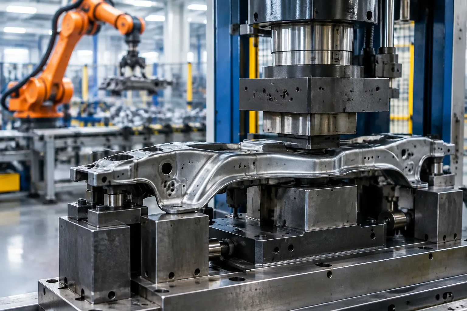
The chassis is the load-bearing and motion-control backbone of a vehicle. Every force between the road and the body passes through it, which means geometric errors in chassis components translate directly into handling deviation, ride harshness, noise, and accelerated wear. Chassis system straightening exists because stamping, welding, forging, and heat treatment all leave distortion in these parts — and because the tolerances that vehicle assembly demands sit well below what those processes deliver on their own.
Modern chassis straightening solutions pair multi-point measurement with intelligent pressure control: the machine maps the part’s actual geometry, computes the correction, presses at calculated positions, and re-measures — so every component leaves the cell verified against spec rather than merely “corrected”.
Why Chassis Accuracy Drives Vehicle Behaviour
Suspension geometry is a chain of angles and distances. A control arm whose bushing bores sit a few tenths of a millimetre off their nominal relationship changes camber and toe; a stabilizer bar with uneven shape accuracy behaves differently left versus right; a bracket welded slightly out of plane pre-loads the whole subframe at assembly. Because these errors combine, chassis plants specify straightness, symmetry, and position tolerances on the individual components and verify them before welding or assembly.
For mixed-production lines, the straightening cell must also change over quickly between part families — which is why parameterised tooling and stored correction programs matter as much as raw press accuracy.
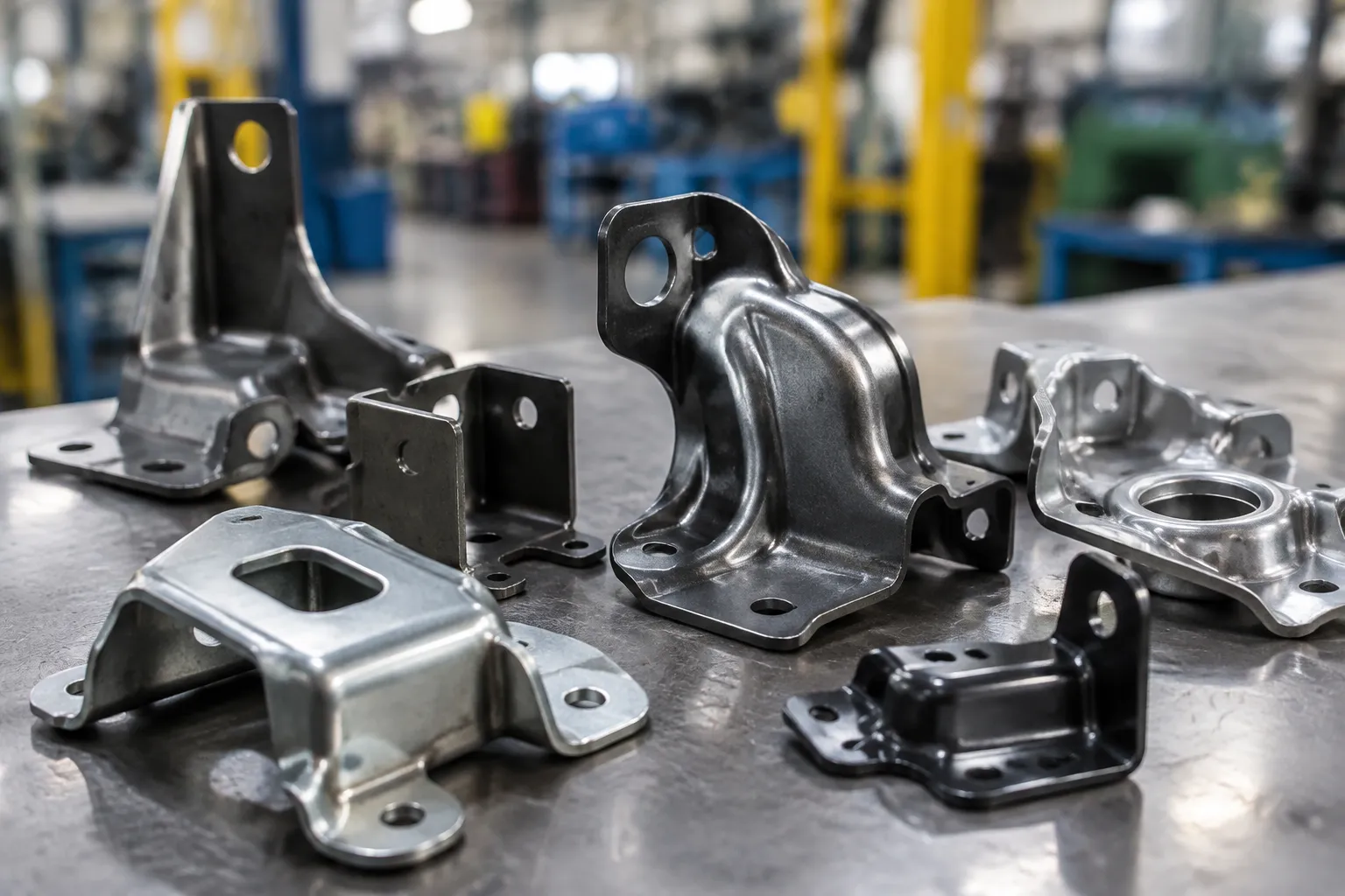
Crossmember and Subframe Brackets
Brackets anchor the chassis structure: they carry loads from the body, subframe, and suspension into the surrounding structure. Their flatness and orientation determine whether bolted joints seat cleanly or are forced into position — a classic source of residual stress and late-stage NVH complaints.
Typical parts processed on a chassis bracket straightening line:
- Front cross member brackets
- Rear cross member brackets
- Subframe brackets
- Suspension brackets
Representative capability targets:
- Flatness: ≤0.2 mm
- Verticality: ≤0.3 mm
- Symmetry: ≤0.5 mm
- Production efficiency: 30–40 pieces per hour
Because brackets are weld-assembly components, correcting them before welding is far cheaper than reworking a completed subframe. Multi-point measurement distinguishes bending from twisting so the press addresses the error mode that is actually present.
Stabilizer Bars and Torsion Bars
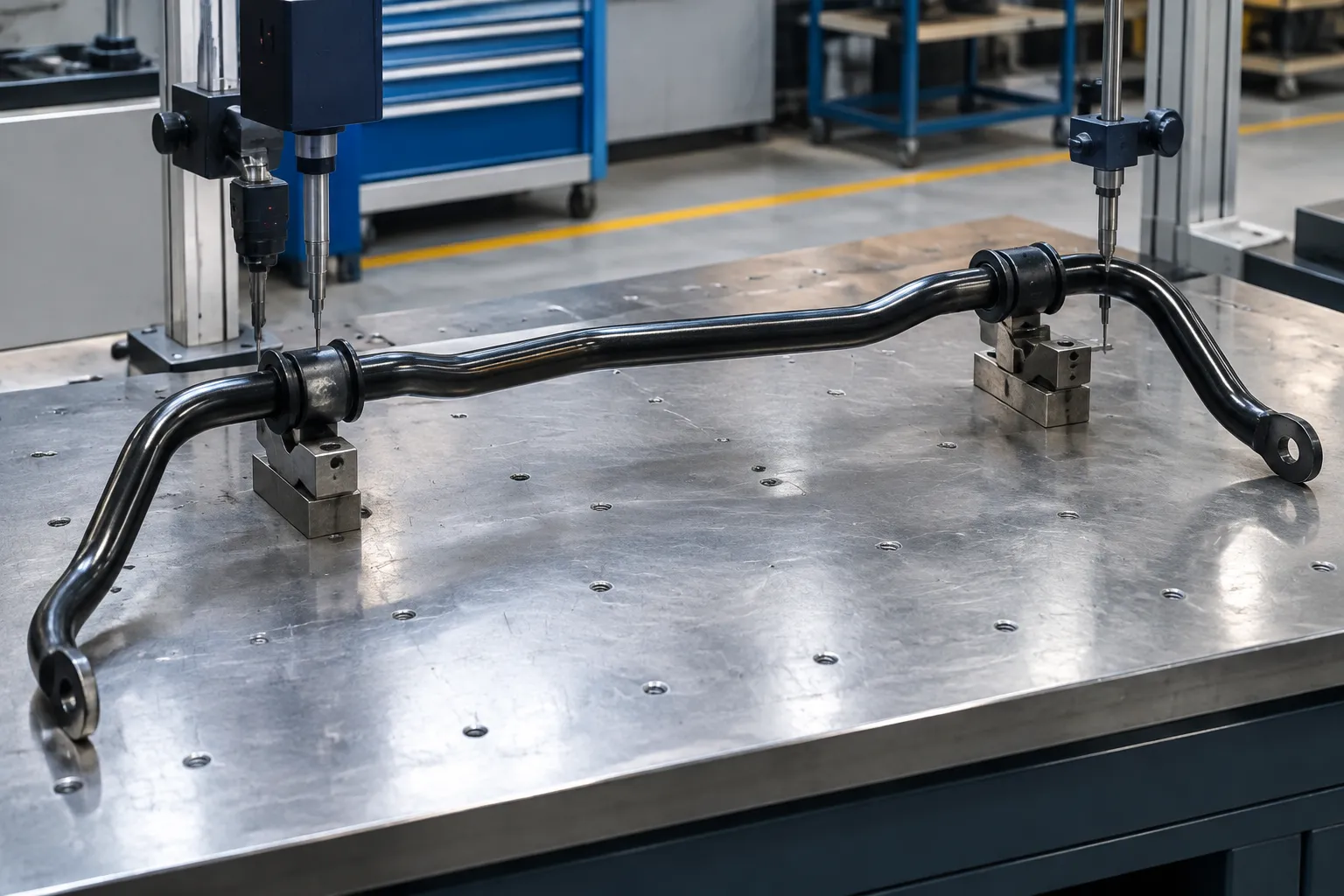
The stabilizer bar is the key component for roll control: it twists as the body rolls, transferring load across the axle. Its shape accuracy — arm angles as well as straightness between the eyes — directly affects handling balance, and asymmetry between left and right arms shows up as uneven roll stiffness.
Parts in this family include:
- Front stabilizer bars
- Rear stabilizer bars
- Torsion bars
- Stabilizer link connecting rods
Representative capability targets:
- Symmetry: ≤0.3 mm
- Angle accuracy: ±0.5°
- Twist angle accuracy: ±1°
- Production efficiency: 40–60 pieces per hour
Angular and twist correction is the differentiating capability here: a bar can be dimensionally perfect yet functionally wrong if its arm angles drift. For related heavy-section spring components, the leaf spring camber correction guide covers the press-and-quench side of the same discipline.
Control Arms
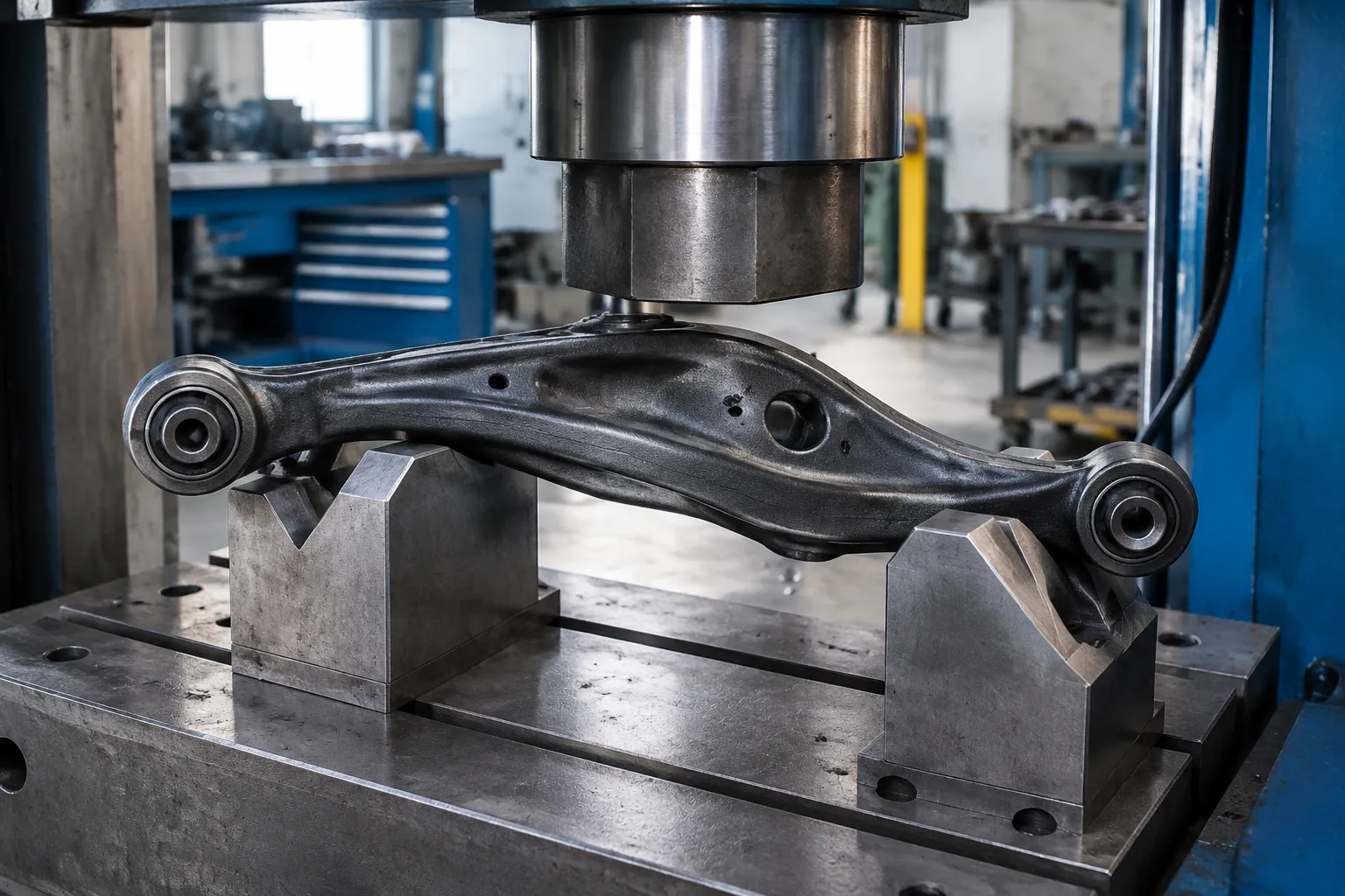
The control arm is the core link of the suspension: it locates the wheel relative to the body, so bore parallelism and bushing-axis geometry define wheelbase and alignment parameters. A distorted arm cannot be compensated by alignment adjustment alone — it introduces compliance error that changes with load.
Typical parts:
- Upper control arms
- Lower control arms
- Front control arms
- Rear control arms
Representative capability targets:
- Parallelism: ≤0.2 mm
- Shaft hole concentricity: ≤0.05 mm
- Torsional deformation: ≤0.3°
- Production efficiency: 35–50 pieces per hour
Concentricity values at the 0.05 mm level push the measurement system to its limit, which is why gauge capability — not just press capability — decides whether a control arm line can hold its tolerance over a production run.
What a Chassis Straightening Cell Must Deliver
Across brackets, bars, and arms, the machine-level requirements repeat. Accurate displacement sensors built into purpose-designed test fixtures give the bend data every correction relies on. A position-controlled loading system — hydraulic or servo — applies stroke depth precisely instead of approximately, raising alignment accuracy while protecting the part. Coordinated axis and clamp management shortens the straightening cycle beat; complete alarm messaging makes abnormal conditions diagnosable in minutes rather than shifts. On-board process memory (16 GB class) with a reserved host-computer link supports traceability, and quick-change, parameterised tooling keeps mixed chassis lines productive. These are the same capabilities that carry engine system straightening at powertrain-level tolerances — chassis work simply applies them to larger, weld-oriented geometry.
Related Chassis Component Guides
Chassis straightening extends across the steering and driveline chain. For steering applications, the steering shaft straightening guide and the steering knuckle process write-up cover accuracy and fixturing in detail; axle-side work is documented for axle shafts and the semi-shaft automatic machine. The automotive parts straightening overview collects the full component map.