
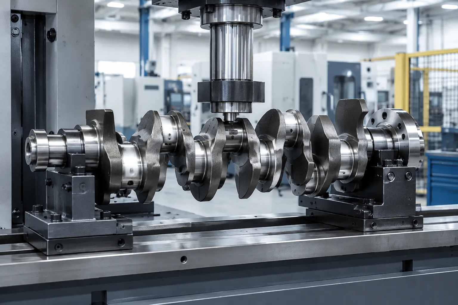
Inside an engine, almost every load-bearing part rotates, slides, or flexes at high speed — which is why dimensional accuracy in this field is measured in hundredths of a millimetre. Forging, heat treatment, and machining all leave stresses in the material, and those stresses release as bend. Engine system straightening is the correction stage that brings crankshafts, camshafts, connecting rods, and valves back inside the tight tolerances that engine performance, NVH, and bearing life depend on.
Modern engine-part straightening cells combine multi-wheel and press-based correction with real-time measurement monitoring, so coaxiality and critical dimensions are verified on every piece rather than sampled occasionally. This article walks through the main engine components that need straightening, the accuracy targets typical for each, and what to look for in the machine features that deliver them.
Why Engine Components Demand Precision Straightening
A bent crankshaft or camshaft does not merely cause vibration — it destroys journal bearings, accelerates seal wear, and pushes oil film thickness outside its design window. A bowed valve stem jams in its guide; a distorted connecting rod alters compression and side load. Because engine parts spin at thousands of revolutions per minute, even a few hundredths of a millimetre of centreline deviation multiply into measurable imbalance and friction losses.
That is why straightening is not an afterthought in engine manufacturing. It sits between heat treatment and finish grinding, and it must hold parts to straightness and runout values tight enough that downstream finishing operations remove only their designed stock. Multi-point measurement locates the actual bend peaks, intelligent pressure control applies exactly the calculated stroke, and the machine re-checks the part after every correction — a closed loop that replaces operator guesswork.
Crankshaft Straightening
The crankshaft is the most heavily loaded rotating component in the engine, converting piston force into torque. After forging and heat treatment, main-journal axis deviation directly affects bearing load distribution and dynamic balance, so the straightening stage determines whether the finished assembly runs smooth or shakes itself apart.
On crankshafts the acceptance values are journal runout figures — main and connecting-rod journals referenced to the axis defined by the centre bores or end journals — and they come from the engine drawing, because grind stock and oversize allowance decide how much correction each throw can absorb.
Because crankshafts are asymmetric forgings with residual-stress fields that differ along their length, the correction strategy matters as much as the machine accuracy. Incremental point pressing at measured peaks — rather than brute-force deflection — keeps the correction stable through subsequent grinding.
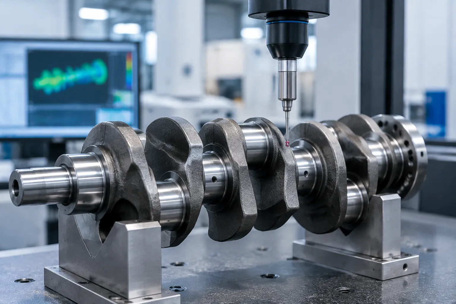
For a deeper treatment of measurement setup, stroke strategy, and acceptance limits on crankshafts, see the dedicated crankshaft straightening guide.
Camshaft Straightening
The camshaft times valve lift with precision measured in angular degrees. Its long, slender profile makes it particularly bend-prone after carburising or induction hardening, and shape accuracy translates directly into valve-event accuracy — and therefore into engine breathing, emissions, and smooth idle.
On camshafts the correction targets are journal runout and axis straightness; lobe-to-lobe timing belongs to the grinding operation, not to the straightening press, and the journal-level tolerances come from the camshaft drawing rather than a generic machine table.
Camshafts reward machines with angular referencing and twist correction, since a part can be straight in one plane yet twisted along its axis. Verifying both before release avoids defects that only surface at engine assembly.
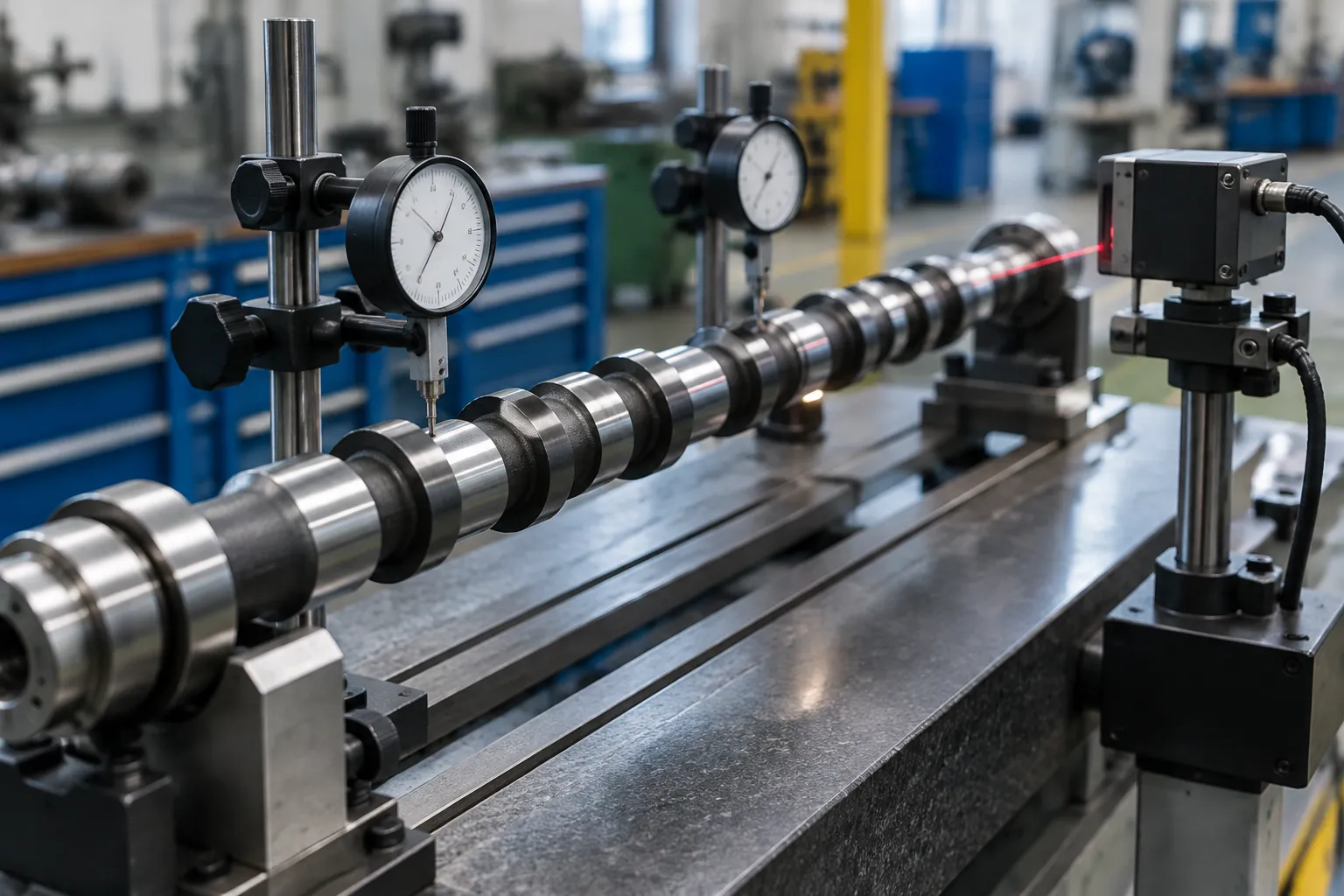
Application notes, fixturing variants, and process parameters are collected in the camshaft straightening guide.
Valve and Connecting-Rod Straightening
Engine valves are thin stemmed parts in which straightness governs the stem-to-guide clearance. Bow in a valve stem shows up as guide wear, oil consumption, and seating problems. The same straightening cell logic — measure, press, verify — applies at smaller scale, with support spacing and load calibrated to the part’s slenderness.
Valve-stem straightness targets sit at the tight end of the whole engine program — commonly in the few-hundredths-of-a-millimetre band and tighter for fine stems — and they are fixed against the stem-to-guide fit from the product drawing, not against a generic tolerance list.
Connecting rods demand their own approach: the rod is a tension-compression member whose bore parallelism and twist affect piston alignment. Rod sleeves and small-end components are corrected in dedicated setups.
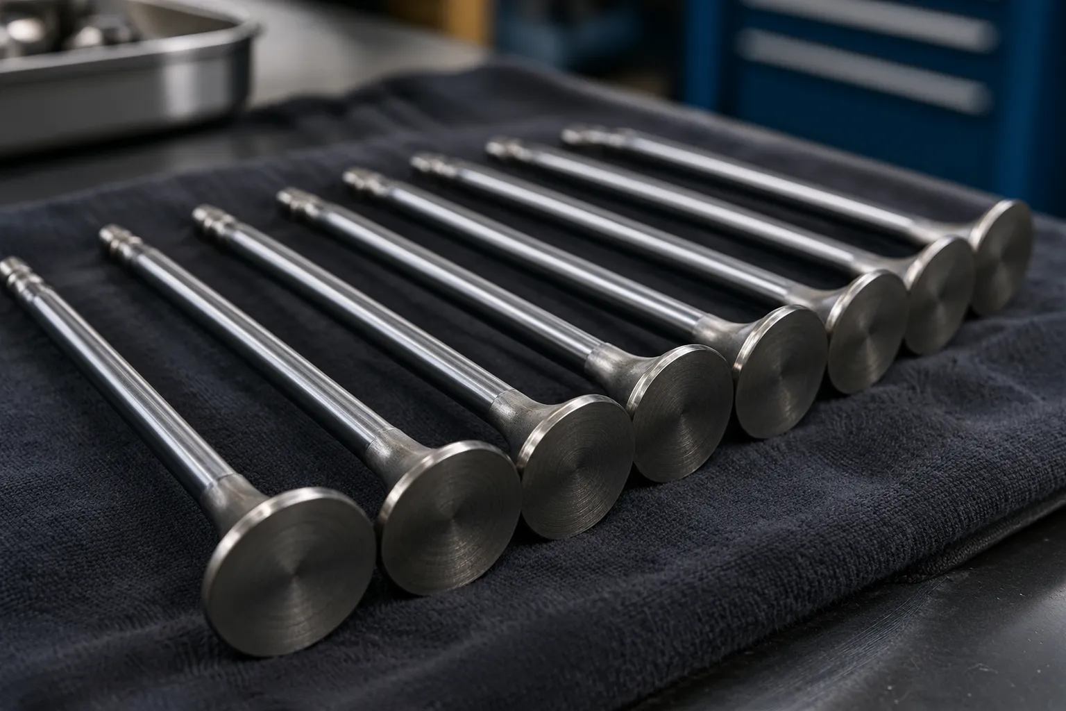
Detailed process write-ups are available for engine valve straightening and connecting rod straightening.
Machine Features That Matter for Engine-Part Lines
Whether the cell runs heavy crankshafts one at a time or valve stems in bulk magazines, the same machine-level capabilities determine whether tolerance holds over a production year:
- High-precision displacement sensing. Test fixtures are built around accurate displacement sensors, because every correction decision is only as good as the bend measurement behind it.
- Closed-loop loading. A high-precision position-controlled loading system improves alignment accuracy and applies stroke depth exactly as computed, not approximately.
- Coordinated motion management. Axes, clamps, and probes are sequenced together to shorten the straightening cycle beat.
- Complete alarm and diagnostic messaging. Abnormal conditions raise specific prompts, which shortens maintenance response instead of hiding faults.
- On-board process memory. A 16 GB memory card stores processing information, with a reserved communication link to the host computer for traceability and SPC.
- Quick-change tooling. Parameterised setup and changeover with automated tool setup keeps mixed-part engine lines viable.
Related Reading
Engine system straightening is part of a wider automotive precision programme. For shafts, gears, and other powertrain components, see the automotive parts straightening overview; for a long-bar production reference with measured results, the 12-metre bar straightening case study documents what a fully automated line achieves in practice.