
An industrial roller is a rotating precision component, not a large round bar. Its bearing journals establish the installed rotation axis while the barrel may carry a specified cylindrical, tapered, crowned or otherwise controlled profile, and the roll may be solid, hollow, fabricated, cast, forged, coated, heated or internally cooled. Those details decide whether pressure straightening is feasible and where force may safely enter the part.
A reliable industrial roller shaft straightening solution defines the roll family, the manufacturing or service stage, the journal datum, the barrel geometry, the support model, the permissible contact zones, the released-state measurement and the sequence between straightening, grinding, coating and balancing. Slender relatives like textile machinery shafts are covered separately.
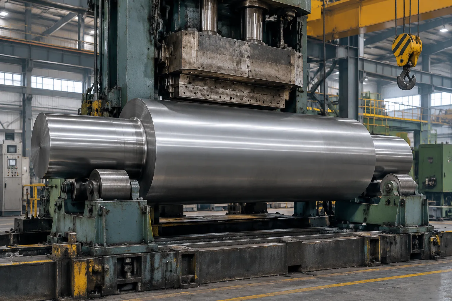
Engineering concept illustration of a rough-machined solid roll blank, not a customer-site photograph. Roll construction, process stage, tooling, force and machine size require drawings and sample tests.
Roller Workpiece or Roller Straightening Machine?
“Roller” can name the workpiece or the machine method, and the search intents are different. This page treats the industrial roll as the workpiece and focuses on point or controlled pressure correction; it does not describe feeding a finished roll through a multi-roll straightener, which is bar and tube equipment.
| Term | Meaning | This page covers it? |
|---|---|---|
| Industrial roller shaft | Rotating roll with central barrel and end journals | Yes |
| Work roll or backup roll | Roll used in a rolling mill or related process | Yes, after roll-specific feasibility review |
| Paper, film or web-handling roll | Roll guiding or processing flexible material | Yes |
| Roller straightening machine | Multi-roll machine for bars, tubes, profiles | No, different equipment family |
| Long round bar | Semi-finished stock without a functional barrel | No, bar straightening is its own process |
Define the Roll Family
The proposal identifies the real construction rather than overall diameter and length: solid forged or cast work roll; backup, intermediate or smaller process roll; hollow tube roll with welded or shrink-fitted journals; fabricated roll with end heads and internal ribs; rubber-, polyurethane-, chrome-, ceramic- or otherwise coated roll; internally heated or cooled roll with bores, channels and rotary-union features; smooth, grooved, textured, engraved or patterned barrel; straight, tapered, crowned or compensated profile; integral gears, couplings, keyways or drive features; new production versus serviced or reconditioned roll; rigid rotor versus a long flexible rotor whose operating shape changes with speed. A solid rough-machined roll accepts a very different load path from a thin-wall fabricated shell, and one recipe cannot safely cover both.
Freeze the Manufacturing or Service Stage
After forging or casting
The blank may carry scale, machining allowance and incomplete journals. Correction can support downstream machining, but measurement must separate surface stock variation from actual axis bend.
After heat treatment, before finish grinding
Material state and major sections are established while grinding stock remains, which makes this the most useful point for correlating the journal axis and barrel before final surface generation.
After finish grinding
Barrel profile, roundness, crown and finish are functional. Direct press or support contact can mark the roll and disturb the generated profile, so correction permission tightens.
After plating or coating
Hard chrome, rubber, polyurethane, ceramic and other surfaces require a coating-specific contact and strain review. A geometry correction that cracks, debonds or locally compresses the coating is not acceptable.
After service
A used roll may contain wear, thermal damage, local yielding, corrosion, cracks, bearing-seat damage or residual unbalance. Straightening must never hide a condition that calls for regrinding, repair or rejection.
| Stage | Datum quality | Main risk | Required decision |
|---|---|---|---|
| Rough blank | Limited, stock-dependent | Surface variation read as bend | Process datum and machining allowance |
| Heat-treated, pre-grind | Journals and body defined | Material strength, crack risk | Force and springback envelope, grinding stock |
| Finish-ground | Functional profile available | Denting, scratching, profile change | Protected contact, full-length measurement |
| Coated | Final surface present | Cracking, debonding, compression set | Coating-owner approval, strain limits |
| Service return | Functional history | Damage misclassified as bend | Inspection, repair, rejection route |
Define What “Straight” Means for a Roll
One dial-indicator value cannot describe the workpiece. The drawing may separately control radial runout of each bearing journal; coaxiality between journal axes; barrel runout relative to the journal axis; straightness of the derived barrel centreline; barrel diameter by axial station; cylindrical, tapered, convex, concave or custom crown profile; roundness and cylindricity; face or shoulder runout; journal-to-coupling or gear relationship; surface waviness, chatter, roughness or texture; static and couple unbalance; and operating deflection, nip pressure, web tracking or product-quality behaviour. Straightening changes global axis relationships; it does not automatically correct local roundness, crown, texture, wear or mass distribution.
Establish the Datum Hierarchy
The solution separates: drawing datums defining the tolerance; bearing journals establishing the installed rotation axis; centres or process datums used by turning and grinding machines; straightening-machine supports and rotation devices; barrel and journal sensor tracks; balancing-machine supports and correction planes; and the final machine bearings, nip or process reference. These references relate but never substitute. Centres can stay stable for grinding while being damaged or irrelevant to the final bearing axis, and a single barrel runout trace blends journal eccentricity, barrel form, support error and actual bend, the same layered datum problem found in machine tool spindle shaft straightening.
Measure Journal Axis and Barrel Profile Separately
Roll-shop practice uses roll-specific measuring technology, including two-point C-frame measurement and dedicated inspection methods, because roll diameter and profile behaviour and journal-axis behaviour require structured measurement of different kinds.
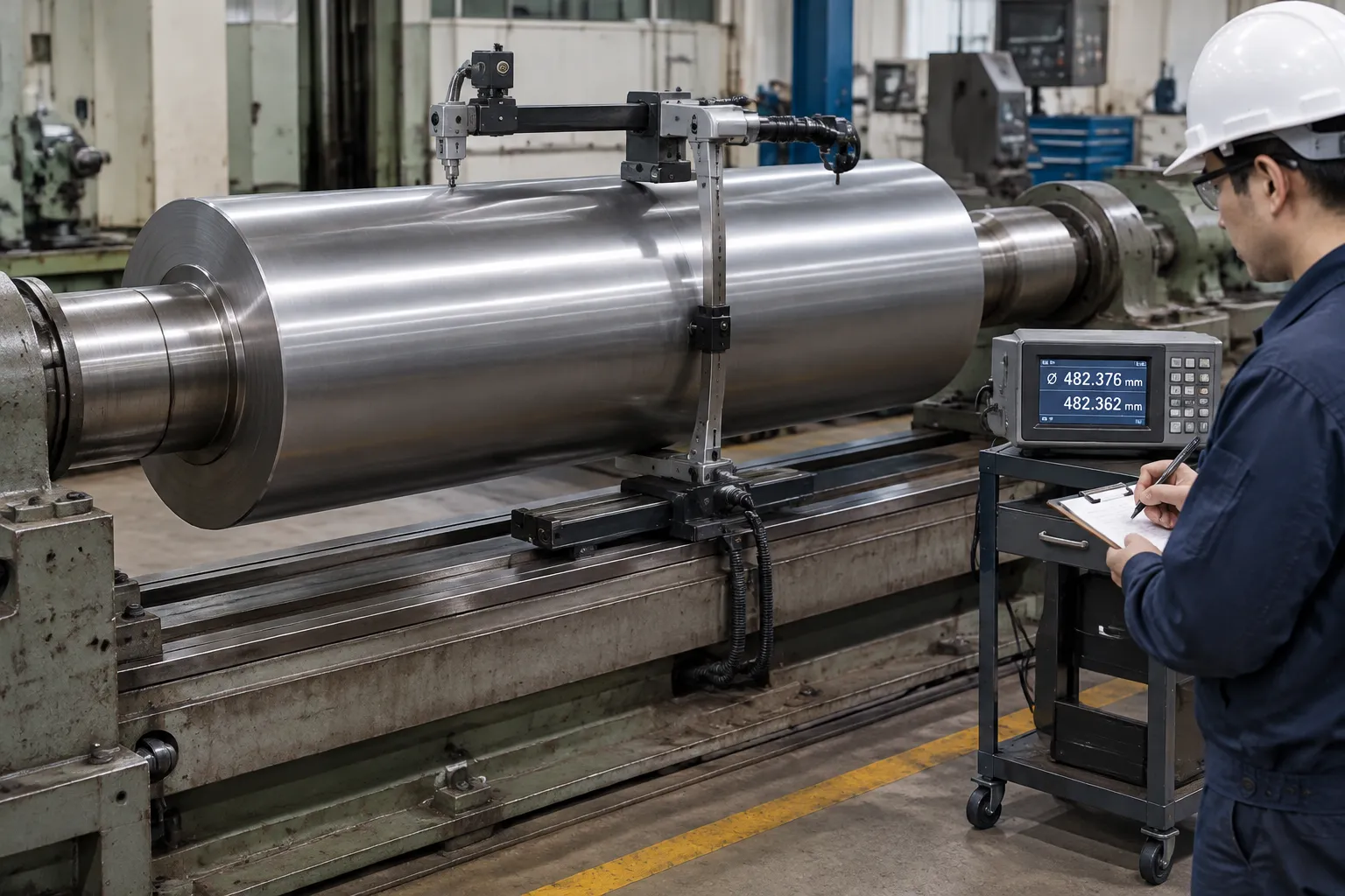
Concept illustration: a roll supported on its journals with a traveling two-point barrel gauge; probe type, contact force, station spacing and profile evaluation follow the drawing.
| Measurement track | Main output | Interpretation risk |
|---|---|---|
| Left and right journals | Functional rotation axis, journal runout | Local roundness or damaged seats biasing the axis |
| Barrel, two-point gauge | Diameter and profile by axial station | Does not alone show eccentricity to the journal axis |
| Barrel, single-point runout sensor | Barrel position relative to rotation | Mixes form, eccentricity and support error |
| Faces and shoulders | Axial runout, assembly location | Chamfers and burrs needing masks |
| Internal bore and channels | Wall distribution, structural condition | Separate internal measurement required |
| Balance reference planes | Mass-axis relationship | Does not define geometric straightness |
For crowned rolls the algorithm compares the measured profile with the intended crown, not with a perfect cylinder. For grooved or textured rolls the feature pattern is masked or measured with a suitable method.
Control Sag, Support Reaction and Temperature
Long heavy rolls deflect under their own mass, and the observed curve changes with journal support position, roller width, contact stiffness, temperature and rotation angle. The measurement recipe fixes exact journal support coordinates and profile; whether the roll sits on centres, journal rollers or bearing-equivalent supports; the sag treatment and mathematical model; multiple angular positions; contact-probe force or non-contact standoff; roll temperature and stabilization; released-state measurement after correction; and correlation to the roll grinder, balancing machine or customer installation. Thermal bow is treated separately: a roll that bends only at operating temperature may not be safely corrected from one cold measurement, and heating or cooling channels, shell thickness and the operating thermal profile require engineering review.
Build a Safe Contact Map
Typical protected zones
- finished barrel surface, crown and texture;
- chrome, rubber, polyurethane, ceramic or other coating;
- bearing journals, seal tracks, finished fits;
- shoulders, fillets, section transitions;
- keyways, splines, threads, cross-holes;
- rotary-union passages and internal channels;
- welds, shrink-fit interfaces, end-head transitions;
- local hardened zones or repaired areas;
- identification marks and balance-correction features.
Correction principles
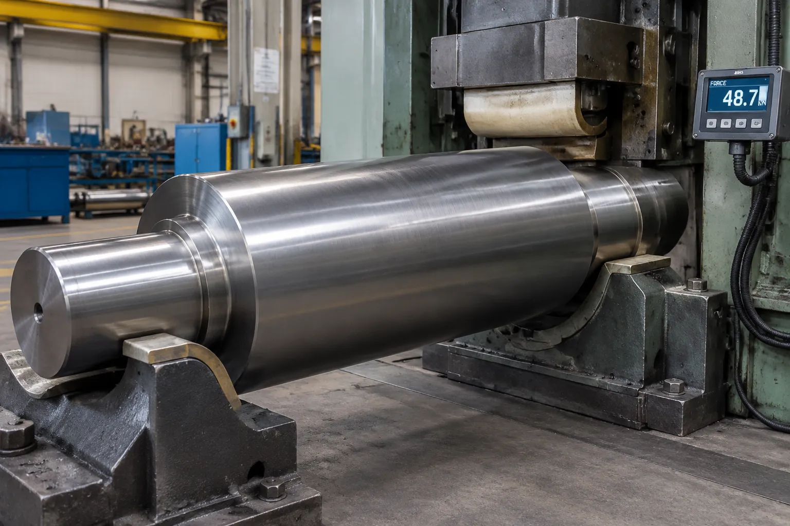
Concept illustration: the protected finished barrel stays outside the press frame; correction is confined to an approved exposed shaft span. Not every roll provides such a span.
- prefer approved rough-machined process lands before final grinding;
- broad radiused shoes and supports matched to the local diameter;
- never transmit a point load through a thin hollow shell;
- no edge loading at shoulders and barrel ends;
- controlled axial movement where required;
- force and displacement monitored through the complete stroke;
- correction count and accumulated strain limited;
- full unload before judging the result.
Solid Roll versus Hollow Fabricated Roll
| Construction | Potential advantage | Main straightening risk | Required evidence |
|---|---|---|---|
| Solid forged roll | Continuous load path, predictable section | High force, hardened surface, crack risk | Material state, hardness, force and springback trials |
| Cast roll | Integral body and journals | Brittle microstructure, casting defects | Metallurgical approval, inspection route |
| Hollow tube roll | Lower mass, long span | Shell ovalization, denting, collapse | Wall map, seam and end-head design, structural analysis |
| Fabricated roll | Custom internal structure | Weld residual stress, discontinuous stiffness | Weld map, ribs, end-head interfaces, NDT |
| Coated roll | Final functional surface present | Coating damage or debonding | Coating strain and contact limits, post-check |
The same cross-section logic that governs hollow shaft straightening applies to hollow rolls, with journals, end heads and a functional barrel added on top, so the recipe is still its own.
Straightening versus Roll Grinding
Grinding addresses barrel diameter and profile, crown or taper, surface finish and texture preparation, limited runout or eccentricity through stock removal, and local wear within the allowance. Straightening potentially addresses global bend of the shaft or roll body, the journal-axis relationship, excessive eccentricity that would eat too much grinding stock, and intermediate geometry before final grinding. Neither process alone proves freedom from cracks, correct internal wall or channel geometry, coating adhesion, acceptable dynamic balance, or the operating thermal shape and product quality. Integrating geometry measurement with roll grinding and inspection supports a coordinated process sequence; it does not justify assuming grinding can safely remove every bent-axis condition.
Straightening versus Balancing
| Condition | Geometry result | Balance result | Correct route |
|---|---|---|---|
| Bent journal or barrel axis | Runout or axis relation fails | Vibration may appear | Correct geometry within limits, then rebalance |
| Straight but mass-unbalanced roll | Geometry passes | Unbalance fails | Balance in defined planes |
| Barrel profile error | Diameter or crown map fails | Balance may pass | Regrind or machine the profile |
| Thermal bow | Cold check may pass | Operating vibration changes | Thermal and operating-state investigation |
| Local journal form error | Journal geometry fails | Support signal unstable | Repair, machine or reject; not a global bend |
Paper- and film-industry rolls appear on balancing-machine makers’ workpiece lists for a reason: balancing handles mass-axis error and does not make a bent roll straight. A roll straightened after balancing needs its final balance reverified, and mass removed during regrinding also reopens the balance question.
The Closed-Loop Process, Ten Steps
- Identify the roll. Recipe from part number, construction, material, coating, profile, stage, drawing revision.
- Inspect and clean. Journals, barrel, coating, welds, transitions, internal passages, known repair areas; approved datum and contact surfaces cleaned.
- Load on approved supports. Orientation, journal seating and lifting points confirmed without dragging the barrel or finished journals.
- Measure journals and barrel. Rotate and reconstruct journal-axis behaviour; measure barrel diameter, profile and runout at drawing-based stations with feature masks.
- Classify the deviation. Correctable global bend separated from journal form error, barrel profile error, shell ovality, coating damage, weld distortion, thermal bow or unbalance.
- Select a safe correction span. Approved process lands or exposed shaft zones only; load path clear of fragile shell, coating, shoulder or internal feature.
- Apply controlled correction. Validated span, force and displacement limits, springback model; stop on abnormal stiffness, slip or sensor behaviour.
- Fully release and remeasure. Judge only the unloaded roll; recheck journals, barrel runout and full profile, because one correction moves several characteristics.
- Inspect and route. Surface, crack, coating, weld or internal checks as required; route to final grinding, coating, balancing or engineering review.
- Record and unload. Identity, recipe revision, before and after maps, correction coordinates, force-displacement curves, alarms, disposition.
Proposed Cell Configuration
- heavy electromechanical or hydraulic press sized from sample force data;
- moving gantry or adjustable workpiece table;
- journal rollers, centres or custom bearing-equivalent supports;
- traveling barrel measurement plus separate journal sensors;
- interchangeable broad radiused shoes and protected pads;
- slow rotation and angular indexing;
- cranes, manipulators or conveyors matched to roll mass;
- force, displacement and recipe control;
- released-state remeasurement;
- interfaces to grinding, balancing and roll-shop records.
The architecture for a rough forged work roll is not automatically suitable for a finished coated web-handling roll; the machine follows the workpiece, as with every family from motor shafts upward.
Sample Test and Acceptance Plan
Representative samples cover: smallest and largest barrel and journal diameters; minimum and maximum length and mass; solid, hollow, cast and fabricated constructions; material, heat-treatment and hardness states; straight, crowned, tapered and textured profiles; rough, ground and coated surfaces; expected incoming bend magnitude and direction; journal and barrel measurement correlation; approved and prohibited correction zones; cold and stabilized temperature conditions; grinding-stock and final-profile requirements; balance verification and customer gauge correlation; and surface, coating, weld and crack inspection after correction. Feasibility, FAT, SAT and production capability stay separate tests, and no third-party roll-grinder or balancing-machine rating converts into a straightening guarantee.
Data Required for a Technical Proposal
- roll and journal drawings with revisions;
- roll function and application;
- solid, hollow, cast or fabricated construction;
- material, heat treatment, hardness, coating;
- barrel profile, crown, taper, texture and surface requirements;
- length, mass, barrel diameter, journal dimensions;
- manufacturing or service stage at straightening;
- incoming bend, runout and profile maps;
- drawing datums and customer measurement method;
- approved support and press zones;
- internal channels, welds, interfaces, prohibited regions;
- grinding stock and downstream process sequence;
- balancing planes and verification method;
- inspection, traceability and reporting requirements;
- representative samples for trials.
Frequently Asked Questions
Can a finished roll barrel serve as the press surface?
Do not assume so. Finished profile, coating, texture and surface integrity are functional. The default solution uses approved rough process lands or exposed shaft spans unless the roll designer validates a protected barrel-contact method.
Can grinding remove a bent roll condition?
Grinding corrects profile and limited eccentricity within the stock. It may not restore the required journal-to-barrel axis relationship without excessive removal, so measure the complete geometry first.
Can a hollow roll be straightened like a solid roll?
No. Shell thickness, seams, end heads, ribs and internal channels change stiffness and collapse risk, so the load path gets its own structural and sample-test review.
Balance before or after straightening?
Final balance follows the last operation that materially changes geometry or mass. A roll straightened or reground after balancing requires balance verification.
Does low runout prove the barrel profile is correct?
No. A roll can show low rotational runout and still carry the wrong crown, taper, roundness or waviness; profile and axis relationship are evaluated separately.
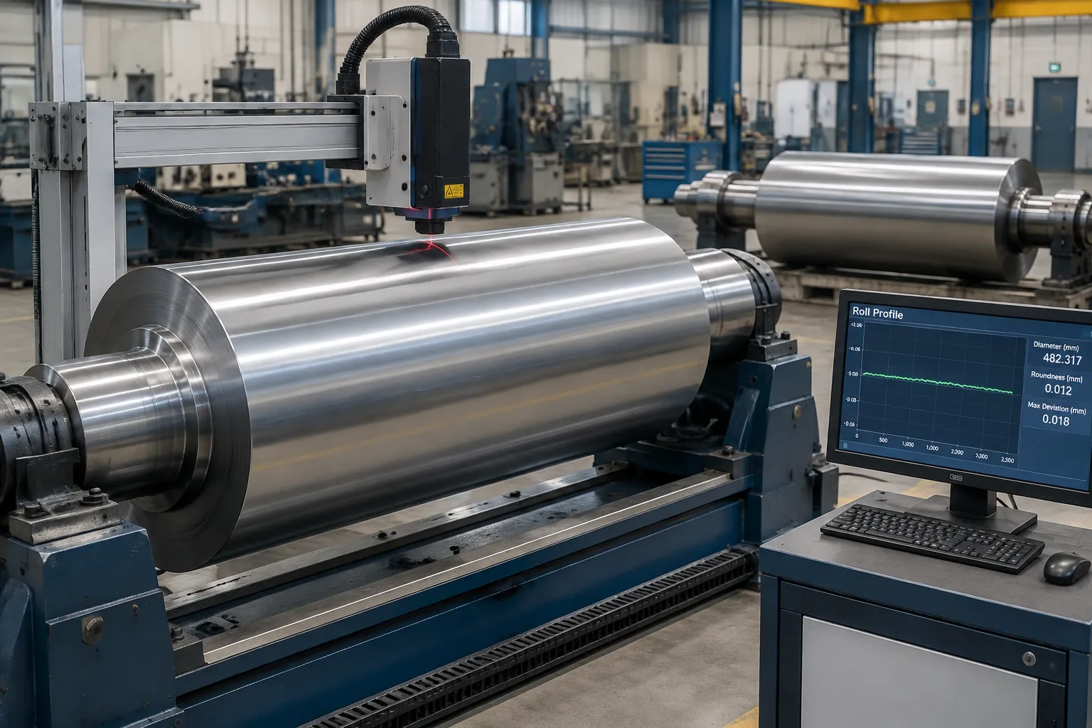
Build the Solution Around the Real Roll
Industrial roller shaft straightening solutions are developed around the actual roll construction, manufacturing stage, journal datum, barrel profile, protected surfaces, safe load path and the downstream grinding and balancing route. The result may be a heavy rough-roll cell or a precision protected-shaft station, but machine selection follows evidence from drawings and sample trials. Send the roll drawing, construction, material and coating, incoming geometry, grinding allowance and balancing method, and the measurement strategy, tooling map, correction envelope, sample matrix and traceable acceptance plan follow. Adjacent families such as textile shaft straightening and the general shaft-type parts overview complete the picture.