
A machine tool spindle shaft is not simply a precision round bar. Its front and rear bearing seats establish the rotating support axis, while the tool interface, gauge face, drive features and internal drawbar or coolant passages must all stay functionally related to that axis. The same part can carry thin hollow sections, cross-holes, keys, splines, threads, balance corrections and locally hardened surfaces, each of which changes what a correction is allowed to touch.
That is why a machine tool spindle straightening solution starts with a feasibility decision rather than a machine catalogue: is the workpiece a bare spindle shaft at a controllable manufacturing stage, or a finished spindle cartridge with bearings, motor and clamping system already installed? Controlled pressure straightening may be considered for a suitable bare shaft with approved process lands. A complete spindle assembly normally goes to spindle assessment, disassembly and component-level diagnosis before anyone talks about correction.
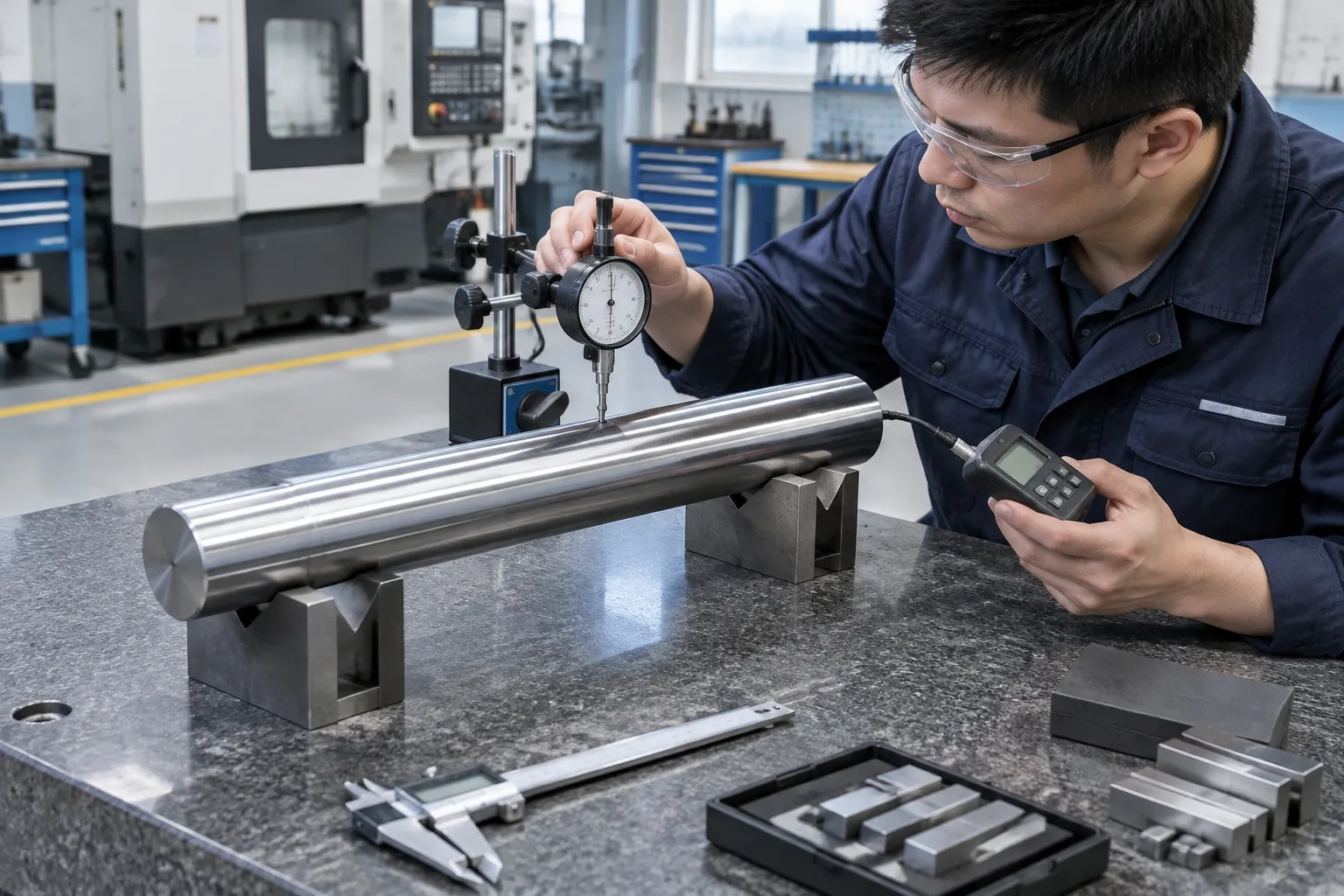
Engineering concept illustration: a bare rough-machined spindle shaft blank supported for controlled correction on an approved process land. Not a customer-site photograph; tooling, support locations, load limits and machine size require drawings and sample tests.
First Define What Is Actually Being Straightened
“Spindle” gets used for several different products, and they do not share one straightening route:
| Workpiece | Typical contents | Pressure-straightening decision |
|---|---|---|
| Bare spindle shaft or quill | Bearing seats, tool interface, bore, drive end | Potentially feasible after datum, material and contact-zone review |
| Rough-machined spindle blank | Machining allowance, designated process lands | Usually the best stage for a controlled sample study |
| Finish-ground spindle shaft | Functional seats, taper, faces, final surface finish | Highly restricted; protected contact, full reinspection |
| Complete spindle cartridge | Shaft, bearings, preload system, housing, seals, drawbar | Not a bare shaft; assess and disassemble first |
| Motor spindle rotor assembly | Shaft plus rotor package, magnets or windings | Requires rotor, electrical, thermal and balance engineering |
| Tool holder or arbor | Separate removable tooling interface | Different workpiece, different acceptance standard |
| Lathe chuck or workholding nose | Workholding interface, assembly features | Interface-specific diagnosis, not a generic shaft recipe |
This page covers the bare machine tool spindle shaft. It does not claim that an assembled electrospindle, cartridge or bearing set can be placed in a press and safely corrected.
Identify the Spindle Family and Interface
A proposal built only from overall length and maximum diameter is a proposal built on sand. The actual construction matters:
- milling, machining-centre, turning, grinding or special-purpose spindle;
- belt-driven, gear-driven, direct-drive or motorized architecture;
- solid shaft, hollow shaft, quill or sleeve-type construction;
- HSK, SK steep-taper, PSC, Morse, proprietary taper, external taper, chuck-mounting or fit-bore interface;
- single-contact or face-and-taper contact system;
- front and rear bearing arrangement, seat sequence and preload concept;
- drawbar bore, coolant-through bore, air passages, lubrication holes, cross-drillings;
- integral pulley, gear, spline, keyway, encoder track, labyrinth or seal land;
- carburized, nitrided, induction-hardened, coated or selectively hardened regions;
- new-production part, repair return or remanufacturing component.
Spindle manufacturers describe automatic tool interfaces such as HSK, SK and PSC as systems built around the tool interface and a flat contact face. The transferable lesson for straightening: the internal taper or fit bore and the gauge face are functional features, never convenient press surfaces.
Freeze the Manufacturing or Repair Stage
After heat treatment and rough machining
Geometry and material state are set while finish-grinding stock remains. With stable centres, reference seats and approved process lands, this is normally the most controllable stage for a feasibility study.
Before bearing-seat and tool-interface finish grinding
Straightening can reduce the stock that grinding would otherwise burn generating the final axis and interface. The plan must still preserve enough allowance at every functional feature.
After finish grinding
Bearing seats, tapers, gauge faces, seal lands and shoulders already carry functional geometry and finish. Support or press contact can dent, burnish or distort them, so any correction here demands protected tooling, a restricted load map and complete post-process measurement.
After balancing
Correction changes geometry, stress and the relationship between balance planes. The shaft cannot be assumed to keep its previous balance condition; final balancing belongs after the last operation that materially changes geometry or mass.
After bearing or motor assembly
A bare-shaft recipe does not apply. Bearing preload, raceway condition, fits, rotor position, clamp force, thermal growth and housing alignment all shape spindle behaviour. Route the assembly to assessment and controlled disassembly.
Service or crash return
A crashed spindle can hide brinelled bearings, taper damage, tool-interface fretting, a pulled or bell-mouthed taper, cracked sections, damaged drawbar components, local yielding or thermal distress. A low-speed static runout check alone cannot classify those conditions as a correctable bend.
| Stage | Available evidence | Main risk | Default route |
|---|---|---|---|
| Rough blank | Process datums, stock map | Surface stock masquerading as bend | Establish stable datums, sample-test correction |
| Heat-treated, pre-grind | Material state and geometry clearer | High springback or crack risk | Validate force envelope and grinding stock |
| Finish-ground shaft | Functional seats measurable | Surface marking, form damage | Restricted protected correction or regrind/reject |
| Balanced shaft | Balance record exists | Balance invalidated by correction | Correct geometry first, rebalance after |
| Complete cartridge | Functional test data may exist | Hidden bearing, preload, rotor, thermal effects | Assess, disassemble, diagnose components |
| Crash or service return | Failure history may be known | Damage mistaken for bend | Inspection and repair or rejection first |
Define the Functional Datum Chain
The solution must state which features define the part and which are only temporary process references:
- Drawing datums define the specified geometric relationships.
- Front and rear bearing seats define the installed support axis.
- The tool-interface taper or fit bore locates the tool or workholding system.
- The gauge face or spindle nose controls axial seating and face runout.
- Centres or process journals may support turning, grinding or straightening.
- Drive, encoder and seal features must stay related to the bearing axis.
- Balancing journals and correction planes define the mass-correction setup.
- The assembled spindle and machine structure define the operating condition.
These references relate to each other but never substitute for one another. Accurate centres do not prove coaxial bearing seats. Low runout at an external journal does not prove the internal taper sits correctly on the bearing axis. A good balance result does not prove geometric straightness. The same hierarchy discipline governs simpler shaft projects like motor shaft straightening, and it gets stricter as features stack up.
Separate Straightness, Runout, Form and Spindle Performance
One indicator reading can blend several error sources. The drawing and acceptance plan may separately control: centreline straightness of the shaft body; radial runout of each bearing seat; coaxiality between front and rear seat axes; internal tool-taper runout relative to the bearing axis; spindle-nose or gauge-face axial runout; journal roundness and cylindricity; taper angle, contact pattern, bell-mouth or wear; shoulder, thread, spline, pulley or encoder-track runout; static and couple unbalance; non-repeatable runout, bearing condition and assembled vibration; and tool-point displacement, clamp force, thermal growth.
Straightening can potentially change a global bend or an axis relationship. It does not automatically correct local roundness, taper damage, face damage, bearing defects, unbalance, clamp-force loss or thermal instability.
Measure Multiple Functional Tracks Before Applying Force
Precision-bearing engineering from suppliers such as Schaeffler and NTN treats shaft-seat roundness, cylindricity, coaxiality and runout as inputs to spindle running accuracy, and spindle builders treat tool interfaces, fit bores and monitoring functions as separate features. The practical consequence is a multi-track measurement plan:
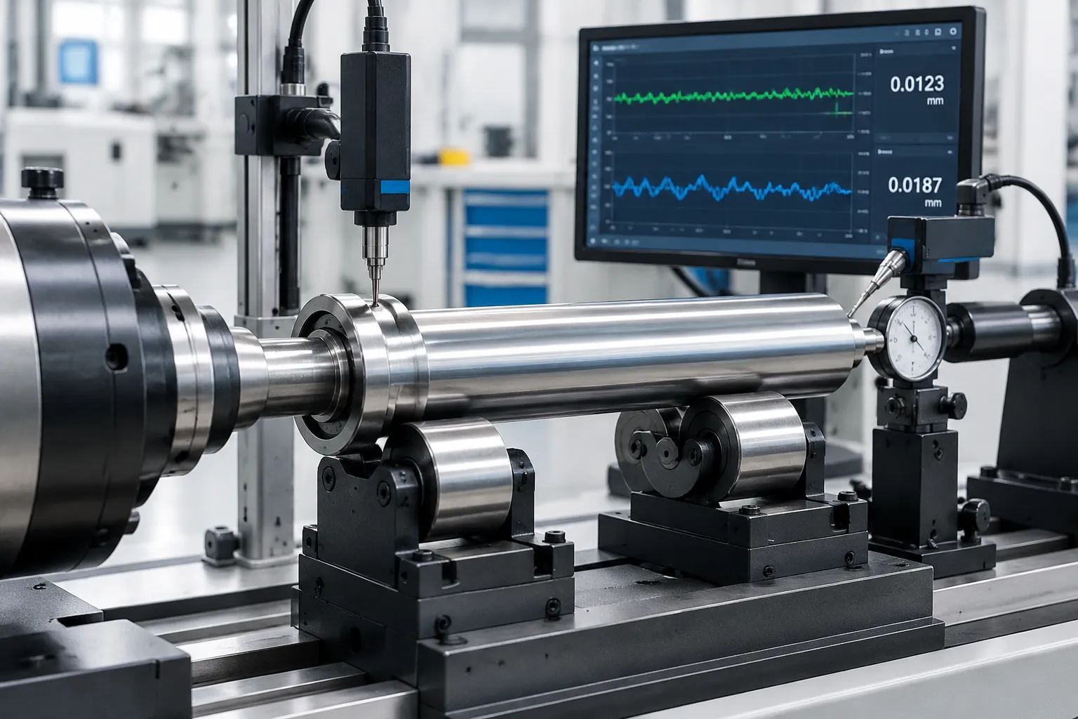
Concept illustration: multi-track inspection of bearing-seat journals, the internal tool interface and the gauge face before any correction decision. Probe type, station spacing, master tooling and allowable uncertainty follow the drawing and gauge-correlation plan.
| Measurement track | Primary question | Typical misclassification risk |
|---|---|---|
| Front bearing seat | Where is the front support axis? | Local lobing or damage reading as eccentricity |
| Rear bearing seat | Coaxial with the front seat? | Support error interpreted as shaft bend |
| Intermediate shaft lands | What is the global bend shape? | Diameter variation biasing a contact probe |
| Internal tool taper or fit bore | Is the tool axis related to the bearing axis? | Taper form damage appearing as pure runout |
| Gauge face or spindle nose | Is axial seating square to the axis? | Burrs, fretting, local dents dominating the reading |
| Through-bore / drawbar bore | Is wall distribution structurally safe? | Hidden thin wall or cross-holes invalidating a load path |
| Drive, encoder, seal features | Will connected components run correctly? | Feature form error mistaken for global bend |
| Balance planes | Is the mass axis acceptable? | Balance cannot identify geometric form by itself |
Rotate the shaft through defined angular positions and verify repeatability before correction. The released-state trace, not the deflected reading under the press, determines the geometric result.
Control Support Error, Sag and Temperature
The measured curve depends on how the shaft is held. Centres, V-blocks, journal rollers, bearing-equivalent supports and final bearings create different boundary conditions, so the measurement recipe fixes: support features, axial coordinates and contact profiles; whether reference journals or centres are qualified before use; shaft orientation and angular index; gravity-sag treatment for long or hollow shafts; sensor force, non-contact standoff and station spacing; filtering and feature masks around holes, keys and interruptions; part temperature and stabilization time; gauge R&R and correlation to the grinder or customer gauge; and a fully unloaded remeasurement after every correction step.
Thermal behaviour is its own decision. Spindle engineering literature separates thermal growth, shaft displacement, bearing condition, tool-nose runout and vibration behaviour. A shaft that passes a cold static check but moves during warm-up may have a bearing, preload, housing, rotor or thermal-symmetry problem, and blind cold pressing is not a substitute for operating-state diagnosis.
Build the Protected Contact and No-Press Map
Default no-press zones
- internal or external tool taper;
- gauge face, spindle nose and precision fit bores;
- finished bearing seats and bearing-abutment faces;
- seal, labyrinth and encoder tracks;
- shoulders, fillets and sharp section transitions;
- threads, splines, keys, keyways, gear teeth;
- cross-holes, lubrication holes, coolant passages;
- drawbar slots and thin hollow sections;
- balance-drill, balance-mill or added-weight locations;
- induction-hardened, carburized, nitrided, coated or repaired zones;
- suspected cracked, burned, fretted or impact-damaged regions.
Potentially approved contact zones
- rough-machined cylindrical process lands with sufficient stock;
- sacrificial support collars or removable process extensions;
- broad cylindrical sections verified by drawing and wall-thickness review;
- purpose-designed tooling interfaces approved by the spindle designer.
Contact approval is local and stage-specific: a diameter that is safe on a rough blank may be prohibited after grinding or hardening.
Protect the Through-Bore and Cross-Section
Most spindle shafts are hollow for a drawbar, coolant delivery, air purge or workholding function, so outside diameter alone cannot size the correction load. The feasibility review covers bore diameter and wall thickness by axial station; taper and counterbore transitions; cross-holes, slots, ports and intersecting passages; internal threads and drawbar features; heat-treatment depth and hardness gradient; shrink fits, sleeves, plugs or bonded components; and permitted ovality and bore alignment after correction.
A three-point load that fixes the external centreline can still ovalize the bore, distort the taper or concentrate strain around a cross-hole. Broad radiused tooling, safe spans and force/displacement limits must be validated on representative samples, the same cross-section-preservation principle that drives hollow shaft straightening.
Decide Whether Straightening Is Even the Right Process
| Observed condition | Likely process route |
|---|---|
| Global bend on a bare shaft with safe process lands | Controlled straightening feasibility test |
| Bearing seats locally out of round or tapered | Grinding, remachining, plating or rejection |
| Tool taper fretted, bell-mouthed, contact pattern damaged | Interface grinding or repair with gauge verification |
| Gauge face locally damaged | Face repair or regrinding, not blind shaft correction |
| Complete spindle vibrating or running hot | Spindle assessment: bearings, preload, balance, resonance, clamp, thermal |
| Shaft straight but balance fails | Dynamic balancing in specified planes |
| Thermal bow appears only in operation | Thermal and assembly investigation |
| No safe load point between protected features | Move the process stage, machine or grind, or reject |
| Crack, burn, local yielding or crash damage suspected | NDT and metallurgical assessment, repair or rejection |
This boundary keeps the straightening machine from becoming a universal repair tool for every spindle symptom.
Straightening, Grinding and Balancing Are Different Gates
Straightening can potentially address
- a global elastic-plastic bend in an approved bare shaft;
- bearing-seat axis relationship before final grinding;
- excessive stock imbalance from a bent rough blank;
- intermediate geometry after heat treatment.
Grinding or machining can address
- final bearing-seat diameter, roundness and cylindricity;
- tool-taper form and contact geometry;
- gauge-face geometry;
- limited eccentricity within available stock;
- surface finish and local functional features.
Balancing can address
- static and couple unbalance in defined correction planes;
- mass-axis error after the final geometry- and mass-changing operations.
Despite listing spindle shafts among classic balancing workpieces, balancing-machine manufacturers are clear that balancing corrects mass distribution, not geometry. Straightening or grinding after balancing means balance must be reverified.
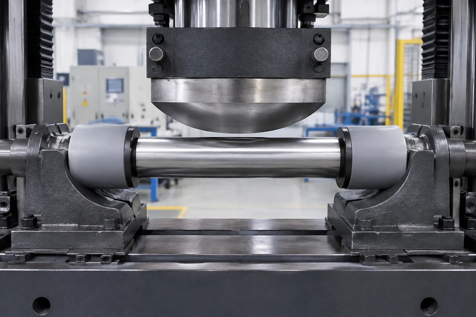
Concept illustration: final runout, tool-interface geometry and dynamic balance are separate acceptance gates; passing one proves nothing about the others.
The Closed-Loop Process, Ten Steps
- Identify the exact part and stage. Recipe selected from part number, drawing revision, spindle family, material, heat treatment, hardness, bore geometry, manufacturing or repair stage.
- Inspect before loading. Clean datum and permitted contact surfaces; inspect seats, taper, gauge face, bore, holes, keyways, transitions and crash-sensitive regions; route suspected damage to inspection before force appears.
- Establish the datum setup. Approved centres, process journals or bearing-seat-equivalent fixtures; verify seating, axial freedom and repeatability.
- Measure the complete functional map. Front and rear seat behaviour, intermediate lands, tool-interface runout, gauge-face runout, drive features; mask discontinuities; confirm repeat measurements.
- Classify the deviation. Global bend versus local form, taper damage, face damage, support error, bore distortion, thermal behaviour, unbalance; correct only the class the validated recipe covers.
- Select a safe correction span. Approved process lands, broad tooling; load path clear of finished seats, taper, shoulders, thin wall, cross-holes, hardened transitions.
- Apply controlled force. Validated span, correction coordinate, force ceiling, displacement ceiling, springback model; monitor the full force-displacement response and stop on abnormal stiffness, slip or sensor behaviour.
- Fully unload and remeasure. Judge the shaft only released; rebuild all relevant tracks because a local correction changes several axis relationships.
- Inspect and route downstream. Crack, surface, bore or hardness checks as required; route to finish grinding, taper and face verification, cleaning, balancing and assembly per the plan.
- Record the result. Part identity, recipe revision, incoming and outgoing maps, correction coordinates, force-displacement curves, alarms, traceability and final disposition.
What a Spindle-Shaft Straightening Cell Can Contain
- electromechanical or hydraulic correction unit sized from sample force data;
- adjustable supports or centres matched to approved datums;
- servo rotation and angular indexing;
- multiple non-contact or low-force runout sensors;
- dedicated tool-interface and gauge-face measurement station;
- broad interchangeable press shoes and protected support tooling;
- force and displacement monitoring;
- automatic springback compensation with released-state remeasurement;
- recipe control, drawing-revision lock, part identification;
- interfaces to grinding, balancing and quality records;
- guards, loading assistance and error-proofing matched to part mass and finish.
The same closed-loop architecture described for the shaft-type parts straightening machine family applies; the spindle project adds its own datum chain, contact map and acceptance logic on top.
Sample Test and Acceptance Plan
Representative samples should cover: minimum and maximum length, diameter and mass; smallest wall thickness and largest through-bore; each tool-interface and spindle-nose family; material, heat-treatment and hardness extremes; rough, semi-finished and permitted finish-ground stages; cross-hole, keyway, spline and transition variations; expected incoming bend magnitude and orientation; stable samples with local form error but no global bend; approved and prohibited press locations; minimum grinding stock after correction; the force, displacement and springback envelope; bore ovality and taper or face preservation; crack and surface inspection after correction; measurement correlation with grinder and customer gauge; balance verification after the final geometry operation; and repeatability across released-state cycles.
Sample feasibility, FAT, SAT and production capability are separate tests, and no bearing, spindle, grinder or balancing-machine performance value from a third party converts into a guarantee for this process. Vendor benchmarking for gearbox shafts or any other family follows the same rule.
Data Required for a Technical Proposal
- spindle-shaft drawing and revision;
- spindle type, machine application, maximum operating condition;
- bare shaft, rotor assembly or complete cartridge status;
- manufacturing or repair stage at straightening;
- material, heat treatment, hardness, surface treatment;
- front and rear bearing arrangement and seat datums;
- tool-interface type, taper or fit-bore and gauge-face requirements;
- length, mass and diameter by axial station;
- through-bore, drawbar bore, cross-hole, coolant and lubrication details;
- incoming straightness and multi-track runout maps;
- roundness, cylindricity, taper and face requirements;
- approved support and correction lands;
- prohibited surfaces and damage criteria;
- grinding stock and downstream process sequence;
- balancing planes, grade and method, final functional test;
- inspection, reporting and traceability requirements;
- representative samples for trials.
Frequently Asked Questions
Can a complete machine tool spindle be straightened in a press?
Not as a default process. Bearings, preload, housing fits, rotor components, drawbar and thermal behaviour all affect the outcome. Assess and disassemble the cartridge before deciding whether the bare shaft qualifies.
Can bearing seats be used as supports or press points?
Finished bearing seats are protected functional surfaces. They may serve as measurement datums or carefully engineered supports, but they do not accept correction pressure by default. Approved rough process lands or sacrificial features come first.
Does low tool-nose runout prove the shaft is straight?
No. Tool-nose runout blends the support axis, interface geometry, face condition and measurement setup. The shaft body and both bearing-seat tracks need separate evaluation.
Can balancing fix spindle runout?
No. Balancing corrects mass distribution. It restores neither seat coaxiality, taper form, gauge-face geometry nor straightness.
Can final grinding replace straightening?
Grinding generates final form and removes limited eccentricity while stock lasts. If a bent blank would eat the stock or break the datum relationship, controlled pre-grind straightening earns its place. The stock map decides.
What if the shaft is hollow?
Wall thickness, bore transitions and cross-holes join the load calculation. The plan verifies both the external centreline and the internal cross-section after correction.
What if runout increases only after warm-up?
Investigate bearing preload, housing alignment, rotor heating, cooling, lubrication and thermal growth. A temperature-dependent symptom is not a permanent cold bend.
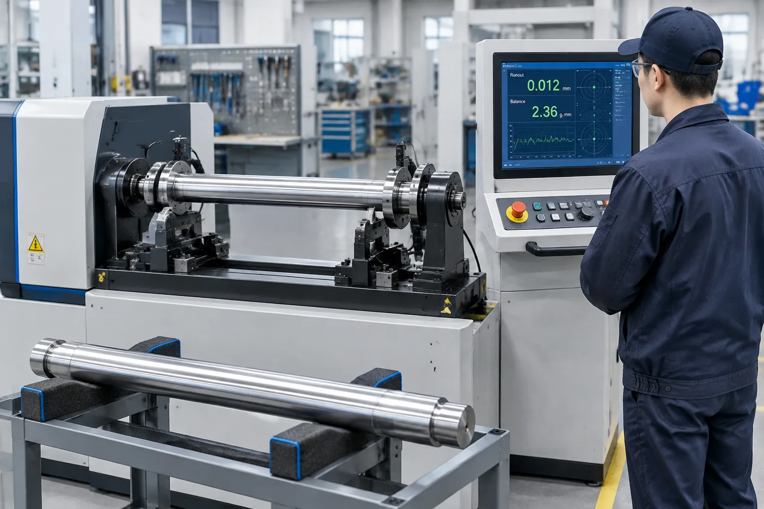
Build the Solution Around the Spindle’s Datum Chain
Machine tool spindle shaft straightening solutions are developed around the actual workpiece stage, the bearing-seat datum axis, the tool interface, the bore structure, the protected contact map, the grinding allowance and the final balancing route. Machine configuration follows engineering evidence from drawings, measurement correlation and sample trials, never a generic shaft recipe.
Send the spindle drawing, manufacturing stage, material condition, bearing and tool-interface requirements, bore map, incoming measurement traces and representative samples, and the feasibility gate, sensor layout, safe tooling, correction envelope and traceable acceptance plan follow as one engineering package.