

A ball screw straightening machine has to solve two problems at once: remove the bend from a long, slender precision shaft, and leave the helical raceway, end journals, and bearing seats exactly as the ball nut and support bearings expect them. This page combines the tested machine specification and trial video with the complete engineering layer behind the straightening solution for ball screw workpieces—manufacturing stage, datum selection, sag handling, raceway protection, multi-point correction, and the acceptance plan that makes the process defensible.

Tested Specification and Machine Video
The tested ball screw family for this trial: 8 mm diameter x 300 mm length, required straightness 0.1 mm. The line is a highly integrated automatic solution consisting of a loading unit, straightening unit, and unloading unit, running the measure–press–recheck loop unattended as shown in the video below.

A ball screw shaft is a precision motion component, not an ordinary threaded rod. Straightening can control shaft bend, but it must not damage the raceway or confuse long-shaft sag, journal error, and groove geometry with permanent curvature. The sections below are the decision layer for exactly that.
Why Ball Screw Shafts Need a Dedicated Solution
| Ball Screw Feature | Straightening Challenge | Project Response |
|---|---|---|
| Long, slender shaft | Self-weight sag can dominate measurement | Freeze support span, orientation, and sag treatment |
| Helical ball raceway | Ordinary probe or roller contact can create false readings or marks | Use approved tracks, non-contact sensing, or dedicated protective tooling |
| Smooth end journals | May provide datum/support features but can be short or stepped | Validate center/journal datum realization and seating |
| Heat treatment or surface hardening | Changes springback and crack risk | Validate material/hardness range and correction limits |
| Ground or finished raceway | Surface damage can affect ball contact | Define no-contact zones and raceway inspection |
| Multiple bend regions | One correction can influence neighboring stations | Build a multi-point bend map and remeasure after release |
| High-speed rotation | Residual bend can excite vibration, but speed performance has other causes | Keep shaft geometry and assembled dynamic validation separate |
| Ball nut/preload system | Nut condition is not measured by bare-shaft straightness | Remove or protect the nut and validate final assembly separately |
The goal is not to make the shaft look straight on one pair of supports. The goal is a controlled shaft geometry that does not compromise the raceway, the journals, or downstream assembly requirements.
Ball Screw vs Lead Screw: Why the Distinction Matters
| Topic | Ball Screw Shaft | Conventional Lead Screw |
|---|---|---|
| Working contact | Recirculating balls in a precision raceway | Sliding thread/nut contact |
| Surface sensitivity | Raceway geometry and finish are critical | Thread flank and surface remain important but the contact mechanism differs |
| Nut relationship | Preload, ball circuit, and matching affect assembled behavior | Nut clearance/friction system differs |
| Straightening concern | Protect raceway and preserve journal/raceway relationship | Protect thread profile and functional journals |
| Final validation | Bare-shaft geometry plus nut/assembly checks as specified | Drawing and screw/nut functional checks as specified |
Both convert rotation into linear motion, but their contact systems and validation priorities differ. Ball-screw-specific tooling decisions should not be copied from a lead screw process without sample evidence.
Freeze the Manufacturing Stage Before Straightening
Before raceway finishing
Correction before final raceway grinding leaves allowance for later processing and reduces contact risk to the finished groove. But later heat treatment, grinding, or stress release can change the shaft again, so downstream verification remains necessary.
After heat treatment
Heat treatment introduces distortion and alters springback. The project must know hardness, case depth, core condition, and whether the candidate correction zones can tolerate the required strain.
After raceway grinding or finishing
Finished grooves require strict contact protection: supports, probes, drive elements, and press tooling must not dent or polish the ball track. Post-finish correction requires representative surface and crack validation.
With the ball nut installed
Straightening with the nut installed can damage the nut, balls, return system, or matched preload condition. Define a bare-shaft process, or an explicitly engineered protection/removal procedure.
Define the Controlled Characteristic
Do not treat “ball screw accuracy” as one undivided requirement. The drawing may separately control:
- shaft straightness or axis straightness;
- journal circular or total runout relative to a datum axis;
- raceway-related runout or another feature-specific characteristic;
- lead/travel deviation;
- journal diameter, roundness, and coaxial relationship;
- raceway profile, surface, and hardness;
- assembled preload, torque, vibration, or positioning behavior.
Straightening can affect some geometric relationships, but it does not automatically correct lead accuracy, raceway profile, or nut preload. Separate shaft straightness from runout and TIR characteristics before approving a shop-floor indicator method.
Datum Selection for Ball Screw Shafts
Center holes
Center holes may reproduce a machining or grinding axis when they are specified, clean, and undamaged. Their role in final acceptance must be confirmed: a stable center setup is not automatically the functional bearing axis.
Bearing journals
Two bearing journals can provide a functional reference when they correspond to the drawing and the assembly. Journal form, spacing, surface condition, and contact method influence the realized axis.
Mathematical reference from measured journals
The machine can support the shaft physically while deriving a reference from selected journal measurements. This method must state how the axis is associated, how sag is handled, and how it correlates with the customer gauge.
Raceway-derived measurement
If acceptance specifically references the raceway, a feature-aware method is required: a sensor seeing the helical groove cannot be interpreted like a probe on a smooth cylinder. Keep drawing datum, machine support, and acceptance reference separate in the plan.
Long-Shaft Sag and Low-Force Measurement
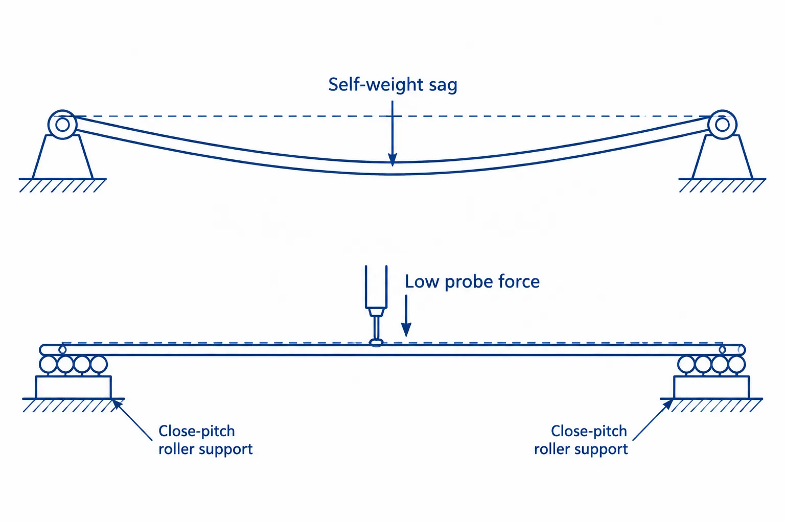
Long ball screws deflect under their own weight, so support span, intermediate supports, and probe force all change the observed curve:
| Measurement Variable | Main Risk | Control |
|---|---|---|
| Support span | Changes gravitational deflection | Freeze coordinates in the recipe |
| Intermediate supports | Reduce sag but can over-constrain the shaft | Validate number, height, and release sequence |
| Probe force | Can deflect a slender shaft | Use suitable low-force contact or non-contact sensing |
| Rotation drive | Can introduce eccentric seating or torsion | Define drive feature and slip detection |
| Axial station | Groove/diameter changes alter the signal | Use drawing-based station coordinates |
| Surface/groove signal | Helical form can look like periodic runout | Separate feature geometry from bend |
| Temperature | Long shafts change length and measurement condition | Freeze part and gauge condition |
| Customer fixture | Different supports produce different results | Perform gauge correlation across the decision range |
A repeatable measurement is not necessarily a relevant measurement. The support model must represent the approved inspection condition, or have documented correlation to it.
Protect the Raceway Groove
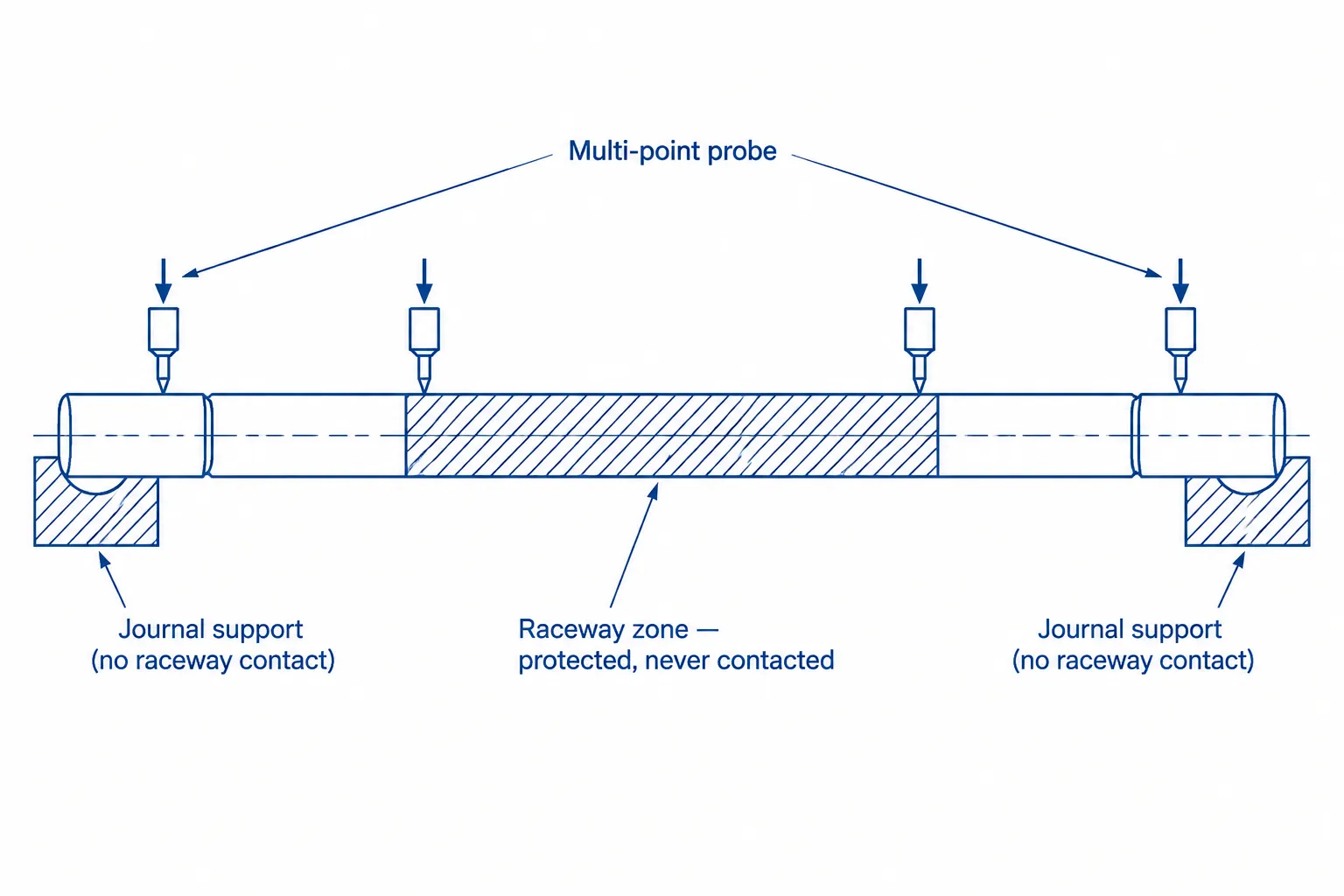
The raceway is a functional rolling-contact surface. Direct contact with an ordinary V-block, narrow roller, probe tip, or press shoe can create marks that are unacceptable even if the shaft becomes geometrically straighter. The protection plan defines:
- permitted contact on smooth journals or temporary process surfaces;
- groove zones that cannot be touched;
- sensor type and standoff for non-contact measurement;
- protective sleeves, matched saddles, or other dedicated tooling when contact is unavoidable;
- cleanliness and particle-control requirements;
- tooling material, contact width, and maximum pressure;
- visual, profile, roughness, or crack inspection after correction;
- tooling life and contamination checks.
A protective sleeve is an engineering option, not proof of safe correction. Its fit, stiffness, load transfer, and removal must be validated so it does not damage the groove or distort the measurement.
Multi-Point Measurement and Correction
Published industrial examples show that long ball screws may require many measurement and correction locations; the exact number depends on length, stiffness, incoming curvature, and tolerance. The bend map should record:
- axial coordinate of each station;
- measured magnitude and angular phase;
- reference/datum condition;
- stations excluded because of groove or feature interference;
- predicted influence of candidate correction points;
- released-part result after each correction;
- maximum permitted attempts and NOK reason.
One large correction at the worst station can change several neighboring readings. A coarse-to-fine or ordered multi-point strategy should be validated with representative parts rather than assumed.
Controlled Correction with Protected Tooling
Localized correction typically uses two lower supports and an upper correction head to create a bending span. For a ball screw, the load path must avoid direct damage to the raceway and end features:
| Correction Variable | What Must Be Validated |
|---|---|
| Support spacing | Bending moment, neighboring-station effect, and sag |
| Press coordinate | Approved zone and relationship to bend map |
| Angular orientation | Groove/feature protection and correction direction |
| Tool contact | Sleeve/saddle fit, contact pressure, and cleanliness |
| Force/stroke | Permanent response, springback, and safety limit |
| Attempt count | No-progress, oscillation, and overcorrection stop rules |
| Released remeasurement | Same datum, support, and station plan |
| Surface inspection | Raceway, journals, and protective-tool contact zones |
Springback and Process Limits
The loaded deflection under the press includes elastic bending. Final geometry must be measured after complete unloading. A control can adapt from released-part response, but it must remain inside validated force, stroke, and correction-count limits. Stop and route the part to review when:
- the measurement is unstable or seating is uncertain;
- correction response is too small or inconsistent;
- the direction repeatedly reverses;
- the maximum attempt count is reached;
- force or stroke approaches the validated limit;
- a raceway, journal, or crack defect is detected;
- the result cannot correlate with the customer gauge.
A Defensible Automatic Cycle
- Identify the ball screw family, drawing, and process-stage recipe.
- Confirm the ball nut is removed or handled by an approved procedure.
- Clean and inspect center holes, journals, raceway, and tooling.
- Load the shaft on the validated reference/support arrangement.
- Verify axial location, seating, rotation, and sag-support condition.
- Measure the agreed stations and separate feature signals from bend.
- Build the multi-point bend map and select an approved correction zone.
- Position supports and protective tooling without contacting prohibited areas.
- Apply controlled correction inside force/stroke/contact limits.
- Fully unload, restore the measurement reference, and remeasure.
- Inspect the raceway and journals according to the surface plan.
- Record the before/after data and route to OK, recheck, or NOK.
Ball Screw Variants That Require Separate Validation
| Variant | Additional Risk |
|---|---|
| Ground ball screw | Finished raceway contact and tight geometric correlation |
| Rolled ball screw | Surface/form condition and process-stage variation |
| Hollow ball screw | Ovalization/collapse and reduced stiffness |
| Long high-speed screw | Sag, critical-speed application, and multi-point curvature |
| Short large-diameter screw | Higher force and limited correction spans |
| Stepped journals | Datum choice, shoulders, and feature transitions |
| Integrated gear/spline end | End-feature protection and functional reference |
| Preloaded matched nut assembly | Preserve matching/preload and validate after reassembly |
Do not copy one recipe across these variants without sample evidence.
Machine and Data Modules
| Module | Project Definition |
|---|---|
| Loading/transfer | Manual, conveyor, gantry, or robot; shaft length and deflection control |
| Part identification | Drawing/family, process stage, and wrong-recipe prevention |
| Datum/rotation | Centers, journals, or calculated axis; drive and seating detection |
| Sag supports | Number, location, height calibration, and controlled release |
| Measurement | Contact/non-contact sensors, stations, masks, and filtering |
| Correction | Moving frame, support span, press head, and protective tooling |
| Surface inspection | Raceway/journal checks before and after correction |
| Changeover | Automatic or assisted setup for length/diameter families |
| Traceability | Initial map, correction history, final map, and decision |
| Quality interface | Customer gauge correlation, reference master, and calibration |
Sample Test and Acceptance Plan
| Validation Group | Representative Samples | Evidence |
|---|---|---|
| Length/diameter range | Shortest/longest and least/most stiff | Sag, support plan, and sensor range |
| Manufacturing stage | Pre-finish, heat-treated, and finished as applicable | Correction response and raceway risk |
| Bend distribution | Good, borderline, single-bend, and multi-bend parts | Map, station ordering, and attempts |
| Material/hardness | Full production range | Force/stroke and springback envelope |
| Raceway condition | Representative finish and surface batches | Contact/inspection result |
| Datum condition | Centers/journals across realistic variation | Seating repeatability and correlation |
| Variant features | Hollow, stepped, end gear/spline if included | Tooling and protected zones |
| Customer gauge | Same parts on both systems | Offset, repeatability, and decision agreement |
Information Required for a Ball Screw Proposal
To convert this page into a quotation, provide:
- complete shaft and assembly drawings with revisions;
- ball screw type, application, and operating orientation;
- ground or rolled raceway and manufacturing stage at straightening;
- solid/hollow construction, material, heat treatment, and hardness range;
- overall length, root/major dimensions, journal diameters, and weight;
- center-hole, bearing-journal, and axial-location specifications;
- controlled characteristics, datums, stations, and tolerances;
- raceway lead/profile/surface requirements relevant to post-correction checks;
- approved support, measurement, drive, and correction zones;
- prohibited contact zones and surface/crack inspection standard;
- ball nut removal, matching, and reassembly requirements;
- customer gauge/fixture, support span, filtering, and rounding;
- incoming bend map or representative reject data;
- throughput, loading method, product mix, and traceability requirements;
- good, borderline, and NOK samples for correlation and trials.
The engineering team then defines the datum, sag-support model, measurement stations, protected tooling, and multi-point correction strategy. Final accuracy, cycle time, and raceway condition should be confirmed from representative ball screws and the agreed acceptance method—not from a generic specification.
Frequently Asked Questions
Is a ball screw the same as a lead screw for straightening?
No. Both are screw shafts, but a ball screw has a precision rolling-contact raceway and a matched nut system. Groove protection and final assembly validation require separate treatment.
Can the machine measure directly on the ball groove?
Only with a feature-aware method designed for the specified characteristic. An ordinary probe following the helix can create a periodic signal that is not shaft bend.
Should a ball screw be straightened before or after grinding?
The process route determines the answer. Pre-finish correction protects the final surface, but later operations can introduce distortion; post-finish correction requires strict raceway/contact validation.
How is sag handled on a long ball screw?
Use a frozen support plan, calibrated support heights, suitable measurement force or non-contact sensing, and correlation to the customer reference condition.
Can a protective sleeve make pressing on the groove safe?
Not automatically. Sleeve fit, stiffness, cleanliness, load transfer, and removal must be tested, and the raceway must pass the agreed post-correction inspection.
How many correction points are required?
It depends on length, stiffness, bend distribution, and tolerance. Published applications show multi-point correction is common, but the actual number must come from the measured bend map and sample trials.
Does straightening correct lead accuracy or nut preload?
No automatic assumption should be made. Straightening controls shaft geometry; lead/travel accuracy, groove profile, and nut preload require their own specified checks.
Is final acceptance measured under press load?
No. Final geometry should be measured after complete unloading and return to the agreed datum/support condition.
Next Steps
The same automatic machine family also covers steel shafts and bars and small motor worm shafts. Ready to quote ball screw work? Contact us with the drawing package listed above, or message WhatsApp +86-13851850644 for a sample test slot.