
Straightening small-diameter medical drill components is a measurement problem before it is a pressing problem. On a workpiece only a couple of millimeters thick, the probe force, the distance between supports, the seating error of the datum and the size of each correction increment all become large compared with the stiffness of the part itself. The same drill can read straight in one fixture and show a completely different runout when it is referenced from the functional shank or from the datum used at final assembly.
This article is the engineering-process treatment of the topic: datum selection, low-force measurement, protected micro-correction and validation for micro-diameter drills. For dated machine test-run records and working videos of medical drill bits, see the medical drill bits straightening test page; the two page types serve different readers and do not replace each other.
The solution outline below is built around a published source project reporting a Ø2 mm × 70 mm workpiece and a 0.05 mm straightness requirement. Those figures are treated strictly as customer inputs, never as demonstrated production results. A numerical guarantee only becomes possible once the controlled drawing, datum definition, gauge method, representative samples and before/after records exist.
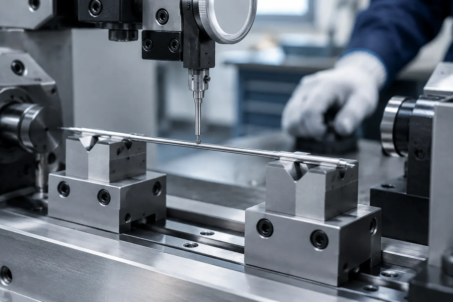
Engineering concept illustration, not a customer-site photograph. Tooling layout, probe selection and correction capacity for micro-diameter drills are always confirmed from the drawing and sample trials.
Reported Project Inputs and Their Evidence Status
| Item | Published Input | Evidence Status |
|---|---|---|
| Workpiece | Small medical drill component | Real part and equipment photos available |
| Diameter | 2.0 mm | Reported in source article; no drawing attached |
| Length | 70 mm | Reported in source article; no drawing attached |
| Target | 0.05 mm straightness | Customer requirement as reported; result report unavailable |
| Material / hardness | Not stated | Must be confirmed |
| Functional datum | Not stated | Must be defined from drawing and end use |
| Process stage | Not stated | Status of teeth, heat treatment, coating and final grinding must be confirmed |
| Production result | Claimed as achieved | Not treated as fact without measurement and capability records |
Why Small Diameter Changes the Measurement
A slender micro-diameter part moves under the very instruments sent to inspect it. The stylus can deflect the workpiece, the supports can impose their own shape on it, and even the part's angular orientation in the fixture can alter the reading. Any credible solution therefore has to define far more than sensor resolution.
Process-stage context matters as well. Blank straightening before grinding is a common requirement on surgical drills, with runout held within roughly 0.1 mm at that stage in typical practice. That value describes a common intermediate-stage expectation, not a universal tolerance; the applicable stage and limit must always be confirmed from the individual drawing.
Functional datum
Drills and deep-hole drills are generally straightened relative to the clamping shank, following the workpiece guidance published by MAE, a principle adopted here as well. The full citation and the datum-choice consequences are discussed on the toothed medical drill straightening page.
Probe force and contact geometry
Stylus force, tip shape and contact position must stay low and stable enough that they neither bend nor mark the component. Before any correction loop is tuned, the measurement system has to demonstrate repeatability on a master or representative part.
Support spacing
Supports have to stabilize the workpiece without forcing it straight. Support positions, radii and contact material consequently become part of the controlled process recipe, not free setup choices.
Straightness versus runout
The reported 0.05 mm figure is expressed as straightness, yet a rotating machine typically reports radial runout or TIR. The drawing has to resolve which characteristic applies before any numerical promise is issued.
Automatic Handling for Small Parts
The source project photos show a compact machine built around a bowl feeder, a transfer mechanism and dedicated measurement and correction tooling. They confirm that automated separation and loading were developed for a small component family. They do not, however, prove any output rate or unattended production period.
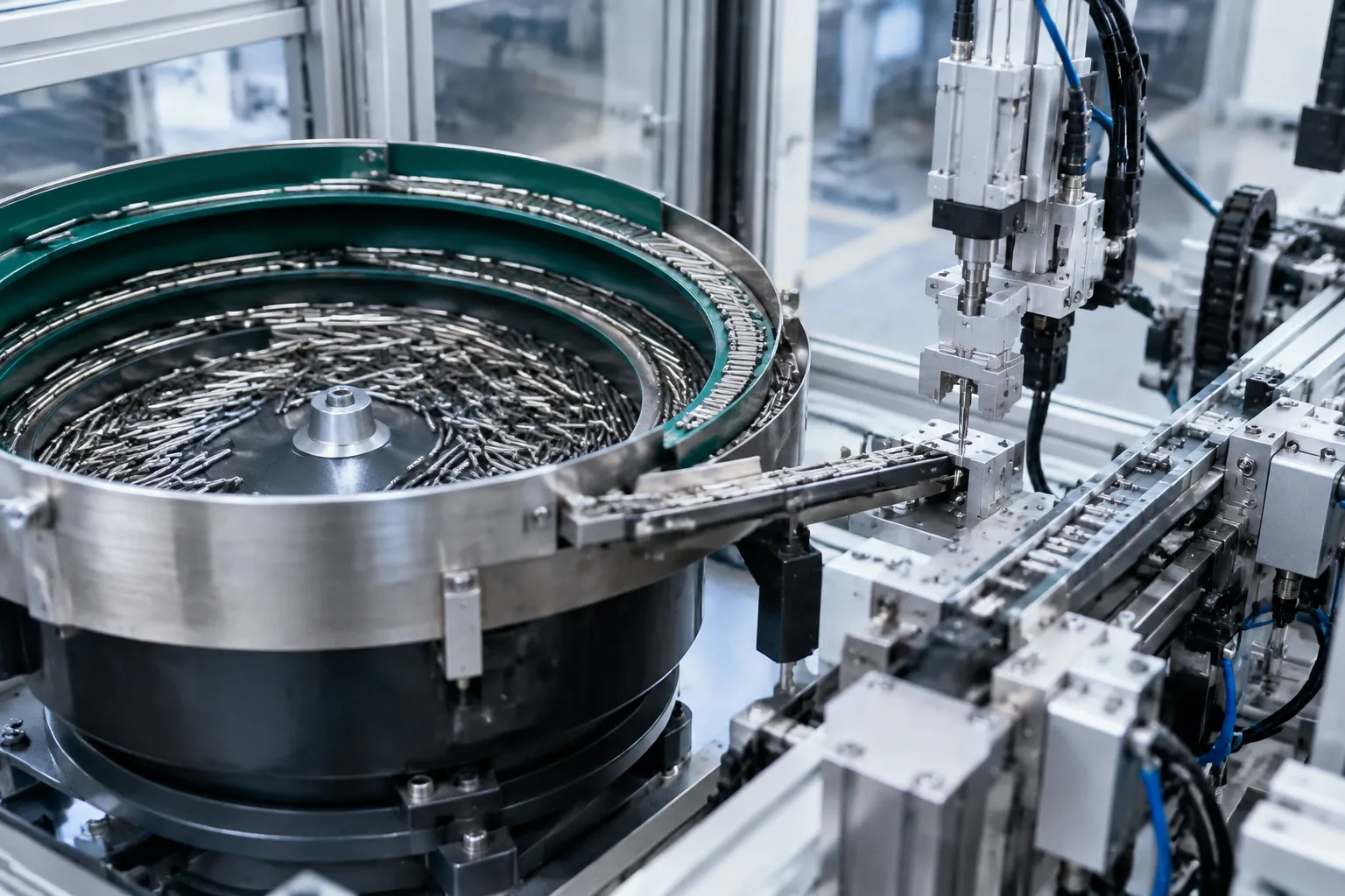
Handling design for micro-diameter drills must be verified against the following list:
- part orientation and end-feature recognition;
- tangling or overlap risk in the feed;
- contact with finished or otherwise critical surfaces;
- transfer repeatability into the measuring datum;
- mixed-part prevention and recipe control;
- reject containment and line clearance.
Recommended Closed-Loop Process
1. Identify and orient
The feeder separates workpieces and presents the correct end in the correct orientation. Presence and seating checks stop the cycle from running on a missing or doubled part.
2. Establish the functional datum
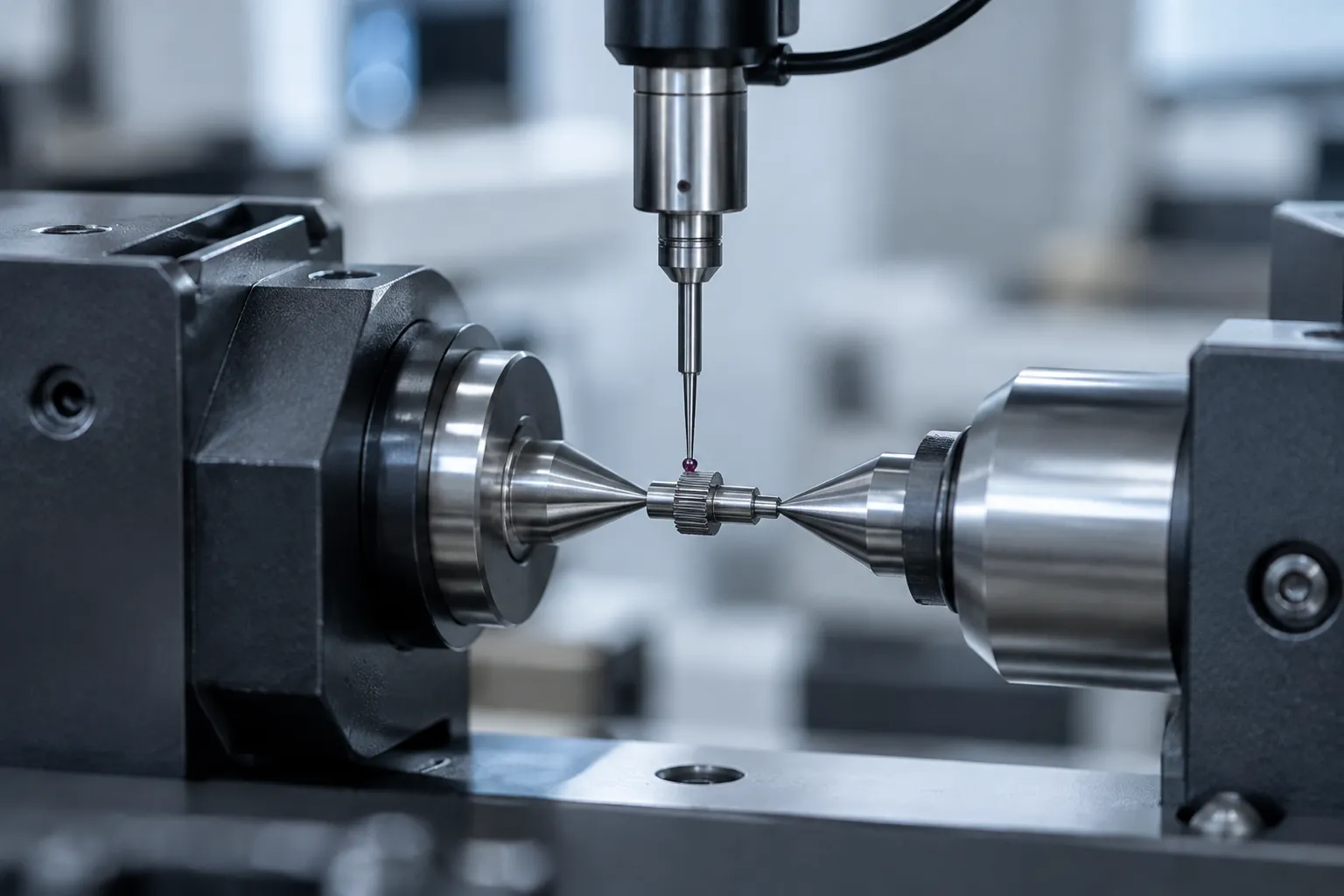
The part is located on its approved shank, centers or drawing-defined references. Clamping force is capped so the fixture cannot introduce a false bend into the measurement.
3. Measure the incoming condition
While the part rotates or indexes, low-force probes read the approved positions. The system records the initial condition and confirms the signal sits inside the validated range.
4. Apply micro-correction
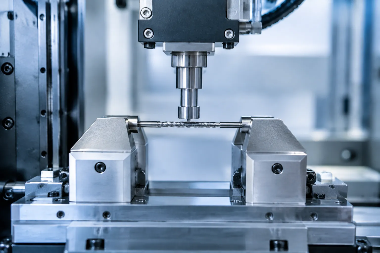
The press tool delivers a controlled, limited displacement at an approved smooth zone. Several small corrections within force and stroke limits are preferred over one large movement.
5. Remeasure
The same datum and probe method are repeated immediately after correction. If the result is still outside the target, a further correction is permitted only within the validated iteration limit.
6. Disposition and record
The part is accepted, rejected or held for engineering review under the drawing-specific rule. Where the approved project scope includes it, the resulting data can be stored or exported.
Validating the 0.05 mm Target
Until the characteristic and datum are defined, the reported 0.05 mm requirement remains technically incomplete. Each item below has to be settled first:
| Validation Item | Required Definition |
|---|---|
| Characteristic | Straightness, radial runout, TIR or coaxiality |
| Datum | Functional shank, centers, journals or a dedicated gauge |
| Measuring positions | Exact axial locations and surfaces |
| Gauge | Resolution, probe force, fixture and calibration status |
| Correlation | Agreement between machine and customer final inspection |
| Incoming window | Maximum bend and permissible shape before straightening |
| Surface acceptance | Allowed marks, burrs and critical zones |
| Capability evidence | Sample size and statistical criterion the customer requires |
The honest public statement is therefore: the source project reported a 0.05 mm target, and achievement stays unverified until the associated records are supplied.
Medical Quality-System Interface
The FDA Quality Management System Regulation applies to this kind of process through the legal manufacturer's quality system; the regulatory discussion in full lives on the toothed medical drill straightening page. The role of the straightening cell stays bounded: it can support controlled records – part and batch ID, drawing and recipe revision, measurement results, correction count and disposition – inside a validated process owned by the manufacturer. The machine itself does not certify FDA or ISO compliance.
Sample Test and Acceptance Plan
- supply representative samples spanning multiple incoming-bend conditions;
- identify material, hardness, heat-treatment and surface state;
- freeze datum, supports, probe force and correction contact zones;
- run repeat measurement before correction to quantify measurement variation;
- record every before/after result and every rejected attempt;
- compare machine readings against the customer's final gauge;
- inspect functional surfaces against defined marks or damage criteria;
- test automatic orientation, transfer and mixed-part controls;
- approve only the demonstrated workpiece and incoming-condition window.
Related Medical Straightening Pages
Adjacent topics on this site: the stepped medical drill straightening treatment for multi-diameter drills, the medical device straightening solutions hub, and the medical drill bit straightener application page. Catalog figures anywhere on those pages are preliminary selection information and must be reconciled with sample results and the final quotation.
What This Solution Does Not Promise Without Evidence
- that the part shown is a finished or approved medical device;
- that every Ø2 × 70 mm component shares one material or datum;
- stable 0.05 mm production output without a defined gauge and capability study;
- any specific cycle time, yield improvement or labor saving;
- zero marks or damage in the absence of an inspection specification;
- that one feeder and tooling set covers multiple part families;
- automatic FDA or ISO 13485 compliance.
Information to Send for a Proposal
For small-diameter drills, the proposal package should lead with the small-part items: probe force versus deflection on thin sections, clamping deformation limits, and feeding stability at the planned rate, alongside the drawing, samples and datum definition. The general package contents are listed on the toothed medical drill straightening page.
Contact the engineering team to arrange a sample-based feasibility and measurement-correlation study.
Frequently Asked Questions
Is 0.05 mm straightness guaranteed for this workpiece?
Not from the published article alone – it is a reported requirement. A guarantee needs the drawing, datum, gauge correlation and representative sample results.
Why is probe force so important on a 2 mm part?
Because the probe and fixture can deflect a slender component and shift the apparent reading. Probe force and support arrangement must be validated as parts of the measurement method itself.
Can the feeder handle several sizes?
Potentially, with change parts – but orientation, overlap, surface contact and transfer must be retested for every family. A software recipe alone is never sufficient.
Can this page reuse the same process as a toothed medical drill?
The closed-loop logic is similar, but the risks differ. A toothed or non-round part needs profile-aware measurement, while a small plain or stepped part is dominated by low-force measurement and handling.
Does the machine make the process FDA compliant?
No. It can support a controlled, validated process and the required records. Regulatory applicability and quality-system compliance belong to the legal manufacturer.
Technical Reference Boundary
External sources – the MAE workpiece guidance for drills and the FDA Quality Management System Regulation – are listed on the toothed medical drill straightening page. They establish engineering and quality-system principles; they do not prove the reported 0.05 mm project result.