
An electric motor rotor is not simply a motor shaft with extra mass. Once a laminated core, squirrel cage, commutator, magnet carrier or other rotor pack sits on the shaft, the workpiece carries new functional surfaces, fragile regions, a thermal history and unbalance behaviour of its own. Pressing, shrink fitting, die casting, welding, brazing, heat treatment and final machining all move the relationship between the two bearing journals and the rotor body. A rotor straightening machine built for these workpieces measures on the journals, protects the pack and gates the correction on balance limits rather than shaft runout alone.
A reliable electric motor rotor straightening solution therefore controls the complete assembly state: the bearing-journal axis, rotor-core runout, exposed shaft geometry, protected no-contact regions, springback, released measurement, and the sequence between straightening, finish turning and balancing.
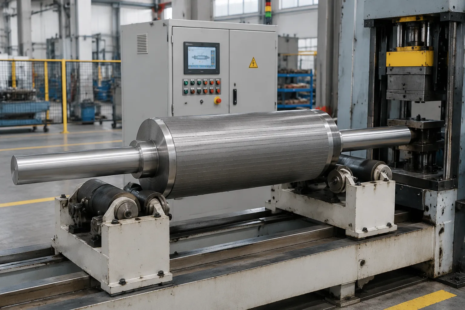
Engineering concept illustration, not a customer-site photograph. Rotor construction, tooling, datum plan, correction force and automation level require drawings and representative sample tests.
Complete Rotor or Bare Motor Shaft?
| Workpiece state | Main geometry question | Dedicated process concern |
|---|---|---|
| Bare motor shaft | Is the shaft axis acceptable before rotor assembly? | Centres, bearing seats, spline, thread, keyway, heat-treatment distortion |
| Shaft with rotor pack | Are both bearing journals aligned after core, cage or magnet assembly? | Pack protection, added stiffness, assembly-induced bend, balance sequence |
| Rotor after finish turning | Do journals and rotor outside diameter correlate in the final datum state? | Finished-surface protection, minimal allowed correction |
| Complete motor | Does the assembled motor meet vibration, noise, current and temperature requirements? | System test; not a straightening-machine acceptance |
Bare-shaft work belongs on the automatic motor shaft straightening page. This page is for the assembled rotor or armature before it enters the stator and housing.
Define the Rotor Family
“Motor rotor” spans very different workpieces, and the proposal has to name the exact one: squirrel-cage induction rotor with cast or fabricated end rings; wound rotor or electrical armature; permanent-magnet or synchronous rotor; traction-motor rotor; generator rotor; rotor with commutator, slip rings, fan, encoder track or coupling feature; solid shaft, hollow shaft or cooling passage; one-piece, pressed, shrink-fitted, welded or otherwise assembled pack; soft-machined, heat-treated, finish-ground, coated or balanced state; and whether the design exposes a safe correction span or buries the shaft completely.
Not every rotor can be pressure-straightened after assembly. Permanent magnets, retaining sleeves, windings, insulation, brazed joints and high-interference interfaces impose strict force, temperature and magnetic-handling limits, so feasibility is proven for the actual construction or not at all.
Freeze the Manufacturing Stage
Shaft before rotor assembly
A bare-shaft project with the best correction access, but correcting here cannot remove distortion that the later interference fit, shrink process, die casting or pack assembly introduces.
After pack assembly, before finish turning
The complete assembly effect is present while machining stock remains on journals or the rotor outside diameter. Equipment suppliers describe rotor straightening at this point as a way to improve bearing-seat geometry before turning and cut unnecessary stock removal, a process-planning principle rather than a universal material-saving guarantee.
After finish turning or grinding
Journals, shoulders and the rotor surface are finished. Tooling contact and indentation limits turn critical, and only approved exposed shaft spans may take correction.
After balancing
Straightening can change the rotor axis, the mass distribution relative to the journals and the previously measured unbalance, so a rotor corrected after balancing returns to the defined balance verification route.
| Stage | Advantage | Main risk | Required recheck |
|---|---|---|---|
| Bare shaft | Maximum correction access | Later assembly reintroduces bend | Remeasure after assembly |
| Rotor assembled, stock remains | Assembly-induced bend visible | Pack and end features need protection | Finish-machining correlation |
| Finish-machined rotor | Functional datums available | Surface damage, few safe press zones | Full geometry and surface inspection |
| Previously balanced rotor | Existing balance data | Straightening invalidates it | Final balance verification |
Define What the Drawing Controls
“Rotor runout” is not one undivided value. The drawing may separately control radial runout of each bearing journal; coaxiality between the two journal axes; runout of shaft extensions, seal tracks, coupling seats or encoder tracks; rotor-core outside-diameter runout relative to the bearing axis; commutator or slip-ring runout; shoulder face runout; straightness of an exposed shaft span; roundness and cylindricity of each journal; rotor-pack axial position, stack condition and end-ring integrity; static and couple unbalance in defined planes; and the finished motor’s vibration, noise and electrical performance.
Straightening changes global axis relationships. It does not automatically correct journal roundness, rotor-stack geometry, electrical defects or mass unbalance.
Establish the Functional Datum
For most assembled rotors the two bearing journals define the installed rotation axis, and electric-motor bearing engineering treats shaft bearing seats and abutment shoulders as controlled geometrical features with explicit radial and axial runout considerations. The customer drawing and selected bearing system still govern. The solution separates: drawing datums and the functional bearing axis; manufacturing centres used for turning or grinding; straightening-machine supports and rotation devices; sensor tracks reconstructing journal and rotor-body runout; balancing-machine supports and correction planes; and the final motor assembly and test references. Centres help machining, but a centre-defined axis is not automatically the axis of the finished journals, and supporting a rotor repeatably does not prove the supports reproduce the customer’s bearing condition.
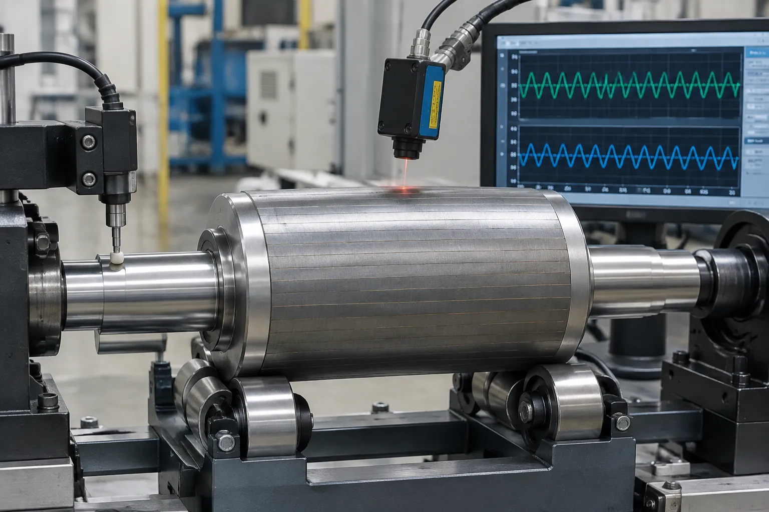
Concept illustration of multiple measurement tracks; it does not prescribe contact sensors on the rotor pack or one universal support arrangement.
| Measurement track | Main output | Interpretation risk |
|---|---|---|
| Bearing journals | Functional rotation axis, journal runout | Local roundness, contamination, probe force distorting results |
| Shaft extensions | Bend outside the bearings | Keyways, threads, splines creating false signal |
| Rotor-core outside diameter | Core-to-journal relationship | Lamination steps, slots, surface features needing masks |
| Commutator or slip rings | Feature runout | Fragile surfaces needing non-contact sensing |
| Shoulders and faces | Axial runout | Chamfers and edge damage to exclude |
| Balance reference mark | Angular correlation | A mark identifies angle, not geometric conformity |
Separate Rotor-Core Signal from Shaft Bend
A laminated rotor surface is not a smooth cylindrical datum. Slots, skew, lamination steps, cast end rings, balancing cuts, adhesive, coatings and local variation all appear in a sensor trace, so the algorithm identifies the rotor type and angular reference; masks slots, keyways, threads, holes and balance-correction areas; uses multiple angular positions to separate repeatable form from global bend; evaluates both journals and at least the drawing-relevant rotor feature; refuses to convert a local lamination or end-ring signal into a heavy press command; and compares the released result with an independent gauge or balancing support where required. If the rotor outside diameter is finish-turned relative to the journals after straightening, the acceptance plan states which geometry is intermediate and which is final.
Protect the Rotor Pack and Electrical Features
The rotor pack is a prohibited correction contact unless the design owner explicitly approves a dedicated fixture. Typical no-press and no-support zones: laminated core and rotor slots; squirrel-cage bars and end rings; permanent magnets and retaining sleeves; windings, insulation and banding; commutator and slip rings; fans, encoders and sensor tracks; bearing journals, seal tracks and finished interference fits; shoulders, fillets and section transitions; keyways, splines, threads, cross-holes and cooling passages; welds, brazed joints and locally hardened zones.
Safe load-path principles
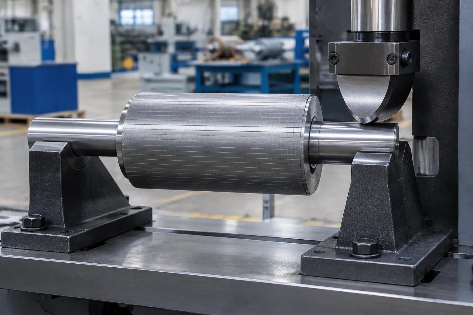
Concept illustration: the rotor pack stays outside the press frame; the three-point load lands only on an approved exposed shaft span. Support coordinates, shoe radius and force limits require representative samples.
- correct only on drawing-approved exposed shaft spans;
- broad radiused shoes and supports matched to the shaft diameter;
- rotor stack kept outside the direct press load path;
- no edge loading near shoulders and fit transitions;
- force and displacement monitored through the complete stroke;
- stop on abnormal stiffness, slip or sensor behaviour;
- correction count and accumulated plastic strain limited;
- full release before the result is evaluated.
Some compact rotors expose no shaft span long enough for a safe three-point correction. The correct decision may be straightening the bare shaft earlier, changing the assembly route, using another correction concept, or rejecting the assembly.
Straightness and Balance Are Different Problems
| Condition | Geometry measurement | Balancing measurement | Correct response |
|---|---|---|---|
| Bent shaft axis | Detects journal, shaft, core runout relationship | Speed-dependent vibration or unbalance signal | Correct geometry if within the approved envelope |
| Mass unbalance, straight journals | Geometry passes | Unbalance magnitude and angle per plane | Remove or add mass by the approved method |
| Local journal form error | Roundness or cylindricity issue | Disturbed support behaviour | Machine or reject; not a global bend |
| Core eccentric to journals | Core runout differs from journal axis | Contributes to unbalance, electromagnetic effects | Decide whether geometry, machining or assembly is responsible |
| Thermal bow | Cold geometry differs from operating state | Changes with speed and temperature | Thermal and operating-state engineering, not cold pressing |
Balancing-machine practice supports rotors on their own journals and measures unbalance in defined planes, a different operation from reconstructing a bent axis and pressing it. Balancing does not straighten a rotor; straightening does not balance one, a coupling that also governs turbocharger shaft work.
Recommended sequence
- establish the assembly stage and functional journal datum;
- measure released geometry;
- straighten only within approved zones and material limits;
- remeasure all geometry after release;
- complete final machining where planned;
- perform or verify balancing in the required planes;
- complete final rotor and motor tests.
If production constraints force a different order, the validation plan must show how later operations affect both geometry and balance.
Control Support Influence and Released Measurement
Rotor mass, support spacing and journal condition shape the observed curve, so the cell defines exact journal support positions and roller profile; rotor orientation and angular indexing sequence; contact pressure and surface protection; sensor force or non-contact standoff; sag treatment for long or heavy rotors; temperature stabilization; loaded versus released measurement state; and correlation to the balancing machine and the final motor gauge. The support condition is part of the measurement definition, whatever machine it lives on.
The Closed-Loop Process, Ten Steps
- Identify the rotor. Recipe from part number, construction, assembly stage, material state, drawing revision.
- Inspect and clean. Journals, keyways, end rings, laminations, magnets and sleeves, commutator, balance cuts and other rejection conditions; approved support and measurement tracks cleaned.
- Load on approved journals or process datums. Orientation, seating and angular reference confirmed without dragging finished surfaces.
- Measure all controlled tracks. Rotate and reconstruct the journal axis, exposed shaft curve and rotor-body relationship; mask discontinuities.
- Classify the deviation. Correctable global bend separated from local form error, loose assembly, pack eccentricity, electrical damage or unbalance.
- Select a safe correction span. Approved exposed zones only; support span, direction, force and displacement limits, rotor-stack clearance confirmed.
- Apply controlled correction. Validated springback model; force and displacement monitored; stop on abnormal signatures.
- Fully release and remeasure. Judge the unloaded rotor; recheck journals, shaft extensions and rotor-body tracks, because one correction moves several relationships.
- Inspect and route. Surface, crack, electrical and assembly checks as required; conforming rotors to final machining or balancing, abnormal parts to engineering review.
- Record the result. Rotor identity, recipe revision, before and after maps, correction coordinates, force-displacement curves, alarms, disposition.
Proposed Cell Configuration
- electromechanical or hydraulic press sized from sample force data;
- protected journal rollers, centres or custom rotation fixtures;
- contact or non-contact sensors for journals, shaft extensions and rotor body;
- angular indexing and feature masking;
- interchangeable broad radiused tools with mistake-proof setup;
- guarded automatic or operator loading;
- force, displacement and recipe control;
- released-state remeasurement;
- part identification and traceability;
- interfaces to finish machining, balancing and quality systems.
Equipment suppliers list manual, chain or fork, portal and robot loading concepts for electric rotors; the final automation level follows the real rotor mass, variant count, surface sensitivity and production flow, exactly as with machine tool spindle shafts.
Sample Test and Acceptance
The representative sample matrix covers: smallest and largest shaft and rotor-core diameters; minimum and maximum rotor length and mass; every rotor construction and assembly method; solid and hollow shafts where applicable; material and heat-treatment states; minimum and maximum incoming bend; all exposed correction spans and prohibited zones; journals before and after finish machining; rotor-core, commutator, slip-ring or encoder features; previously balanced and unbalanced samples; customer gauge and balancing-machine correlation; and surface, crack, electrical and assembly inspection after correction. Feasibility, FAT, SAT and production capability remain separate tests, and a catalogue value is not evidence for a specific rotor family.
Data Required for a Technical Proposal
- rotor assembly and shaft drawings;
- rotor type, assembly method, manufacturing route;
- material, heat treatment, hardness, surface condition;
- part variants, mass, length, rotor-core diameter;
- straightening stage relative to assembly, machining and balancing;
- drawing datums and controlled runout or straightness characteristics;
- incoming deviation distribution and known assembly distortion;
- approved support and press zones;
- protected laminations, rings, magnets, windings, keyways, finished fits;
- correction-count, crack, electrical and surface limits;
- balancing planes, method and required recheck;
- customer gauge and final motor test requirements;
- automation, traceability and reporting requirements;
- representative samples for trials.
Frequently Asked Questions
Can the press push on the rotor laminations?
Do not assume so. Laminations, cage bars, end rings, magnets and windings are functional and damage-sensitive. The default concept keeps them outside the correction load path unless the rotor designer approves a dedicated fixture with validation.
Straighten before or after balancing?
Geometry normally comes first. A rotor straightened after balancing must have its balance condition reverified, because the rotation axis and mass relationship may have changed.
Can one cell process bare shafts and complete rotors?
Possibly, with separate recipes, supports, sensor tracks, tooling maps and validation. The complete rotor adds mass, stiffness, fragile features and balance responsibility.
Does low vibration prove the rotor is straight?
No. Vibration depends on balance, bearings, support structure, electromagnetic forces, alignment, speed and temperature. Released geometry is measured directly against the drawing requirement.
Can accuracy be guaranteed from a CAD model?
No. CAD defines geometry; real samples establish material response, assembly-induced bend, support influence, springback, surface risk and balancing correlation.
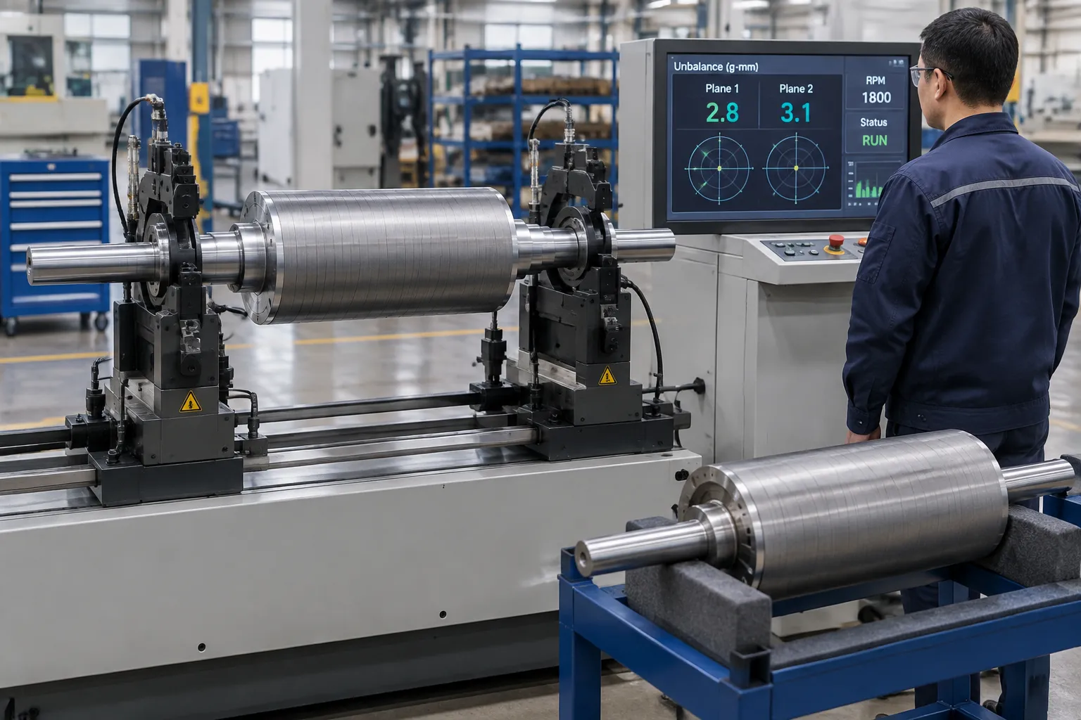
Build the Solution Around the Complete Rotor
Electric motor rotor straightening solutions are developed around the real assembly stage, the bearing-journal datum, the protected rotor pack, safe exposed shaft zones, released geometry and the final balancing route. The equipment may be manual, semi-automatic or fully automatic, but the correction logic stays specific to the rotor family. Send the rotor and shaft drawings, assembly route, incoming runout data, protected-feature map and balancing method, and the measurement plan, tooling, correction envelope, sample matrix and traceable acceptance process follow as one package. The wider machine family is covered in the shaft-type parts straightening overview.