
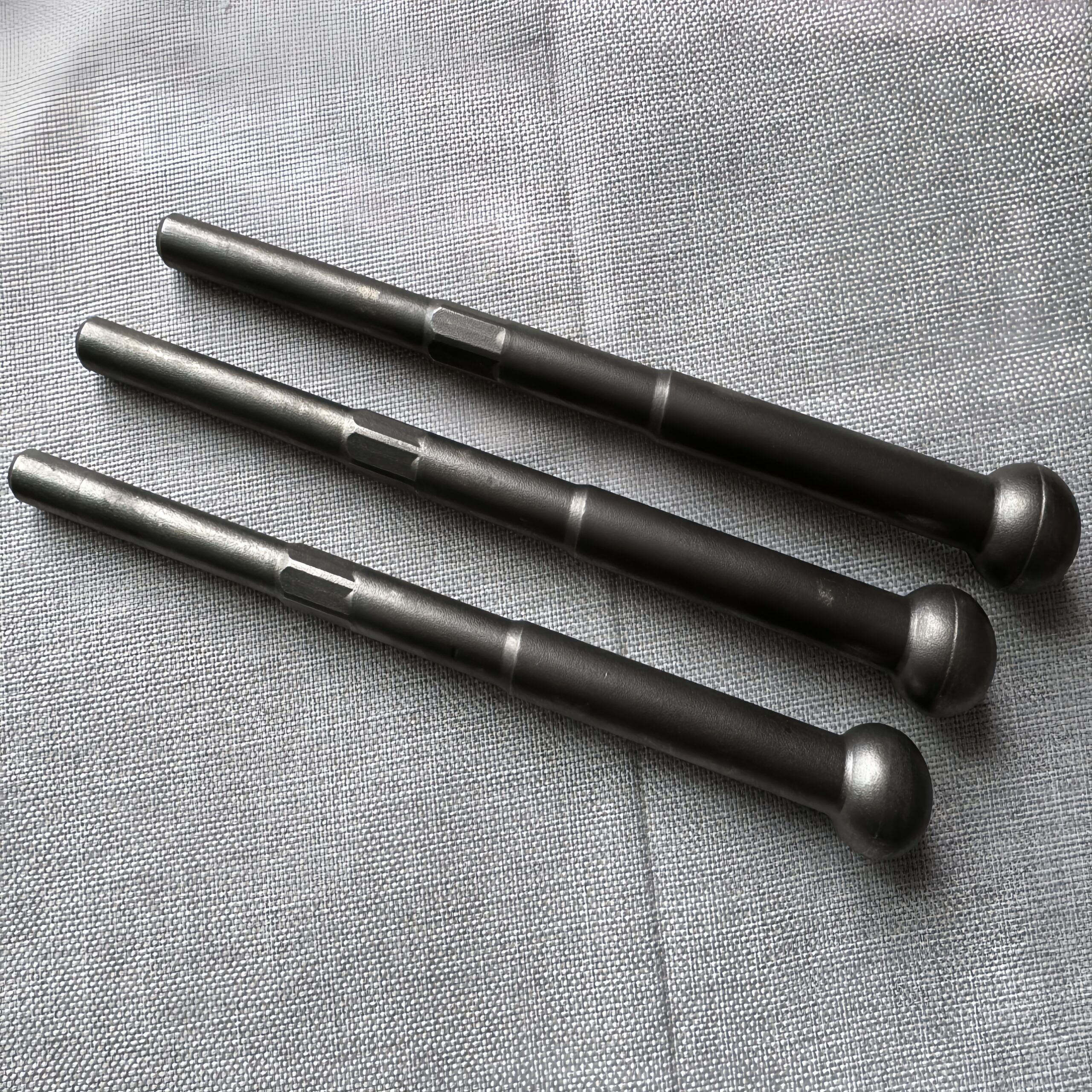
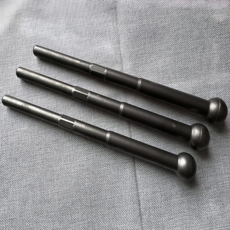
Ball Head Screw Straightening Machine
Ball head screws of 12, 14 and 17 mm diameter and 290 mm length were straightened to 0.15 mm straightness on an AMS-PS1500 straightening machine with a pressing force of about 10 tons. The photo and testing video below are from the actual trial on customer parts.
Ball head screw size: Diameter 12/14/17mm and Length 290mm, Straightness 0.15mm is required
Straightening machine for test: AMS-PS1500, Pressing force: About 10Ton
Why Ball Head Screws Bend
A ball head screw carries its load through a spherical head that must sit centered on the shank. The shank is a slender rod, and slender rods bend: thread rolling and cutting, heat treatment, transport and assembly all leave residual curvature. Because the ball head defines the functional axis of the part, even a modest bend in the shank shows up directly as misalignment, vibration and uneven wear in the joint the screw is driving.
Straightening must respect both features. The measurement datum is chosen so the shank runout is measured relative to the functional axis, and pressing is applied on the shank in a way that does not mark or disturb the ball head.
Test Setup on the AMS-PS1500
For this trial the machine applied about 10 tons of pressing force, which is the range typical for rods of this diameter after heat treatment. The sensors measured runout before the first press and after each subsequent press, and the control system decided the press point and depth from the measured profile rather than from operator judgment. The cycle repeated until the residual bend at every measured point met the 0.15 mm requirement.
Machine Testing Video
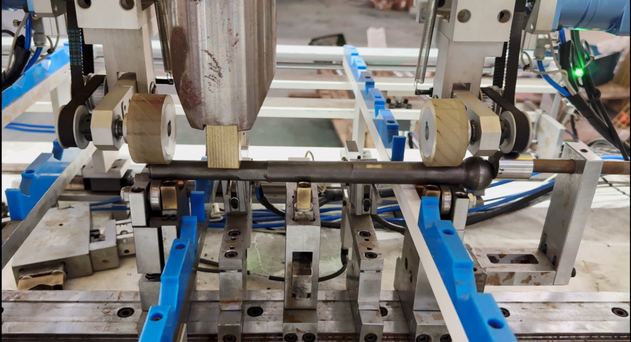
Maching Testing Video:
Datum Selection for Headed Parts
On a headed part, the question that decides the whole straightening setup is what the part rotates about. If the shank is measured between centers that ignore the ball head, the machine can deliver a perfectly straight shank that is still off-axis relative to the head, and the part will vibrate in service exactly as before straightening. The correct approach is to define the functional axis first, which usually means locating on the head features and the bearing journal or thread, and to measure the shank relative to that axis. The same logic applies to any headed or flanged workpiece, from studs to piston rods.
Support placement matters as much as datum choice on a 290 mm part. The distance between supports changes the measured runout of the same bend, so the machine measures with a fixed, documented geometry, and the acceptance number refers to that geometry. When the customer measures on a different setup, the two measurements must be reconciled once, at the trial stage, instead of argued about at delivery.
Acceptance and Repeatability
One straightened screw is a demonstration; a production batch is a process. The trial for this application therefore did not stop at the first good part: additional screws from the same batch were run to confirm that the press point, depth and remeasure cycle repeat across parts with different incoming bend patterns. That repeatability, not the best single result, is what transfers from the trial to your production line.
Related Screw Straightening Knowledge
The same machine family straightens other precision screw geometries. For process background see precision screw straightening, automatic lead screw straightening and threaded rod straightening; a complete cell with loading and unloading for ball screws is described in our complete straightening solution for ball screws.
For morm information about the straightening machine please contact : whatsapp: +86-13851850644
or visit our website: www.straighteningmachinery.com