
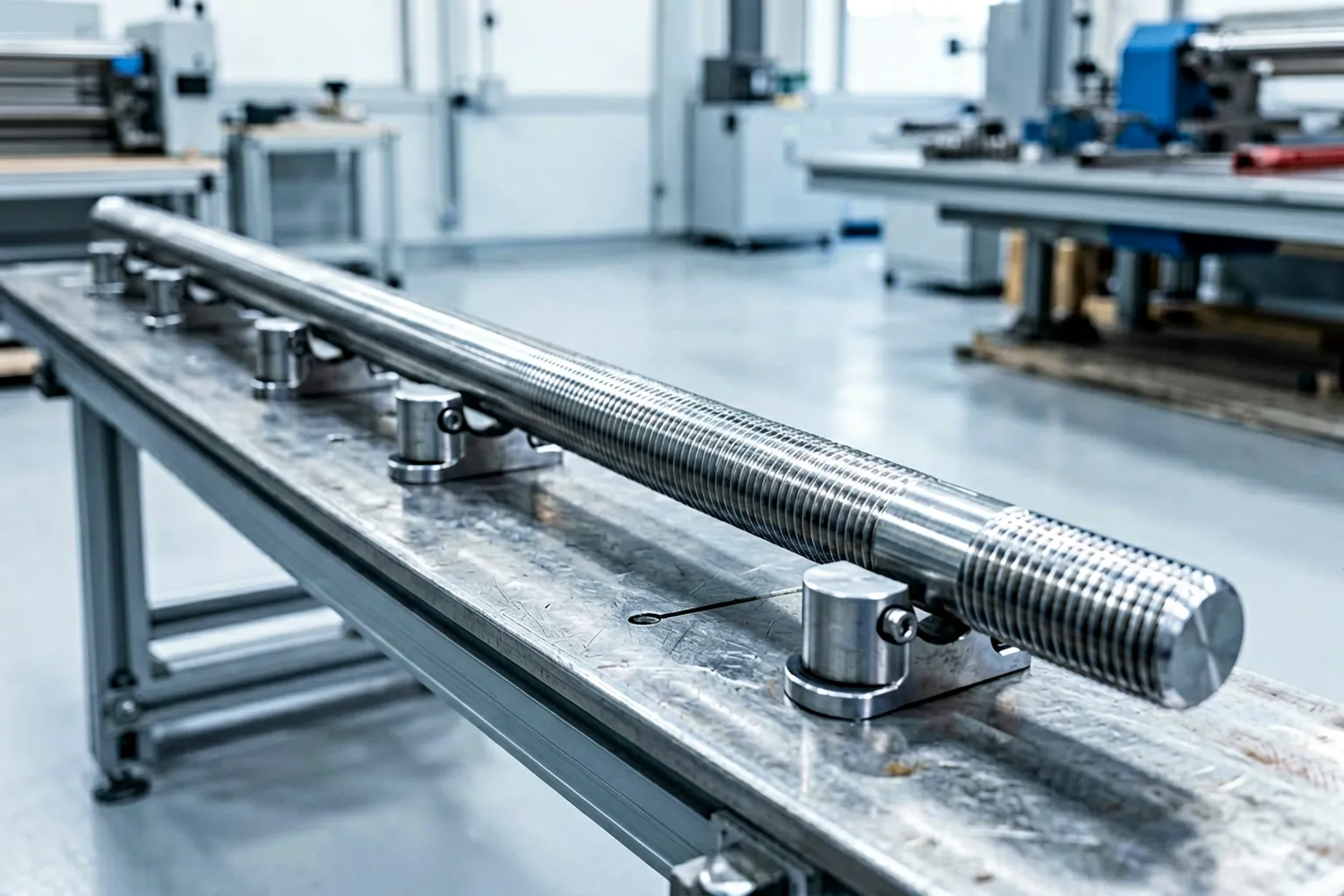
Threaded rod — all-thread bar, threaded stock, cut-to-length stud material — arrives at fabricators and machine shops in a condition that surprises nobody in the supply chain and frustrates everybody after it: bent. Long lengths are shipped as bars that flex in handling; smaller diameters come off coils that remember their curvature. The rod then has to serve as stud stock, tie rods, jack screws and fixture elements, where a straight axis is assumed. Straightening it is genuinely harder than straightening an equivalent plain bar, because there is no smooth surface left to push on, support against, or measure over. The thread itself is both the reason the part exists and the obstacle to correcting it.
This page treats threaded rod straightening as a repeatable industrial process, not a workshop improvisation. It sits inside the fastener straightening family on this site alongside automatic long bolt straightening and short-bolt straightening; the surface-protection discipline that governs all of them is applied throughout.
A workable threaded rod straightening process answers five questions:
- Which threaded rod family is in front of us — diameter range, length, material and thread production method?
- Why did it bend, and is the incoming condition stable enough to define a process against?
- How is straightness measured on a part whose entire surface is a helix?
- Where can force be applied and supported without damaging the thread flanks?
- What does a production loop look like that measures, corrects and verifies rod at batch scale?
The Threaded Rod Family and Its Neighbors
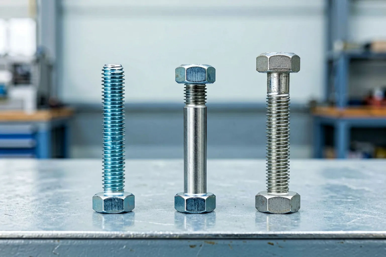
Threaded rod spans a wide industrial range, and the straightening problem changes across it:
- Coil-fed small diameters — the wire-and-bar boundary, where the rod inherits coil curvature and the process is closer to cut-to-length wire lines.
- Mid-range bar stock — straight lengths sold as commodity stud material, bent by handling and transport.
- High-strength alloy rod — quenched and tempered grades used for studs and tie rods, where correction must respect the material’s lower ductility margin.
- Precision stud stock — cut and chamfered rod destined for machinery spindles and fixtures, where the axis tolerance is measured in hundredths of a millimeter.
Two neighbors must be separated from threaded rod before any process discussion, because they are frequently confused with it. A double-end stud carries thread only at its two ends with a plain shank between; its bending concentrates in that plain shank, its strength class and flange-joint role are different, and its handling as a finished fastener is different — it deserves its own process study. A long bolt has a head and, usually, a plain grip length; head geometry gives both a datum and a protection problem that all-thread lacks, as the long bolt page develops. Threaded rod is the pure case: thread everywhere, nothing else.
Why Threaded Rod Bends, and What Shape It Bends Into
Coil memory dominates at small diameters: rod straightened at the mill retains a residual curvature that reappears as soon as the material is free to move — a behavior shared with coil-to-cut wire lines. At bar sizes, bending comes from packaging and transport: rods carried in bundles sag over supports, take set at contact points, and arrive with a gentle single bow mixed with local kinks at banding locations. Cutting rod to length releases residual stress asymmetrically, so a rod that measured acceptable in long stock can bow after cutting. The practical classification for process design: single-plane bow (correctable by classic two-point press work), multi-plane bow requiring rotational measurement and indexed correction, and local kinks — short-radius deviations that respond to point pressing rather than distributed bending.
Measuring a Helix: The Datum Problem
Every measurement method for straightness assumes some form of the part’s axis; on threaded rod, each common method realizes that axis differently, and the differences are not small:
- Rotating between centers or in thread-running sleeves measures runout of the thread effective diameter — functionally meaningful for stud use, and the method most aligned with how the rod will be judged in an assembly.
- Resting in V-blocks measures over the thread crest, which is vulnerable: crest form varies, debris sits in the thread, and the V-block contact rides on the helix, producing a low-frequency waviness in the reading that is geometry, not part error.
- Surface-plate and straightedge methods — the workshop default seen across machinist forums — measure the thread crest gap on one generatrix at a time. They are honest for single-plane bows and blind to twist and multi-plane curvature unless the rod is re-oriented and re-checked at several angles.
- Dedicated measuring stations on industrial cells rotate the rod on its own centers or in sleeve supports and sample multiple sections, extracting bow, twist and local deviation separately — the closed-loop logic shared with automatic shaft straightening generally.
The rule that saves arguments: agree the measurement definition with the customer before agreeing the tolerance. A rod that passes a crest-gap check on a plate can fail a runout check in sleeves, without anything having changed except the definition of the axis.
Correction: Where the Force Is Allowed to Go
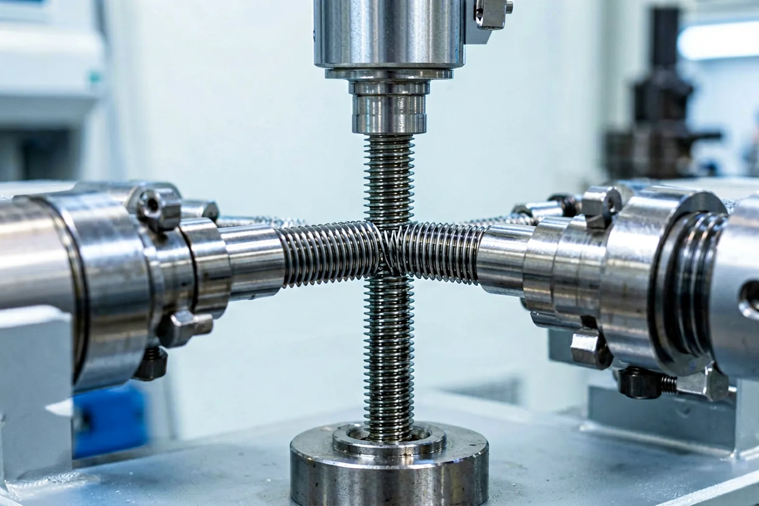
Thread flanks are functional surfaces: they carry the clamp load, and flank damage is not cosmetic. Industrial correction therefore follows three contact rules. Support through sleeves or half-nuts — supports that engage the thread form over several pitches, distributing reaction force into flank roots rather than onto a single crest line. Press through form-matched pads or, at minimum, through pads of a material softer than the rod that cannot bridge and bruise individual crests. Never point-load a crest — the classic workshop shortcut of pressing a threaded rod in a plain V-block between flat anvils puts the full correction load on one or two thread crests, and the resulting flattened helix is a rejected part even when the axis reads straight afterward. The mechanics of the correction itself — measure, support span set, incremental press, release, re-measure — follows the standard two-point discipline: several small corrections outperform one heroic bend, and on high-strength grades the margin between correcting and cracking narrows enough that incremental work stops being a preference and becomes the rule.
Common Failure Modes
Recurring failure patterns: crest bruising from unprotected supports, discovered at assembly when a nut seizes mid-travel; chasing the helix — an inexperienced setup reading thread waviness as bend and correcting geometry that was never wrong; springback underestimation on work-hardened coil stock, where the rod springs back most of the way and the operator corrects twice as often as the process plan assumed; post-cut distortion on rod straightened in stock lengths and cut afterward, which releases stress and returns a bow; and mixed-lot behavior — rods of the same nominal size but different mills and heat treatments correcting differently on identical machine settings, which is the statistical argument for measuring every part rather than sampling.
A Production Loop for Batch Straightening
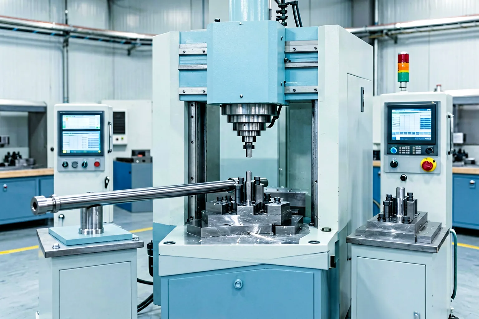
At batch scale the loop is: incoming measurement of every rod in the defined sleeve or center setup, deviation classified by plane and location, correction applied through protected tooling with the rod oriented to the measured high side, re-measurement after release — because springback is real and unconditional trust in the first press is how rework is created — and a final runout record attached to the batch. Rods outside the correction window route to a defect stream rather than into endless re-press cycles; the sorting logic mirrors the NOK discipline described across straightening line practice on this site. The measurement-versus-correction cycle time, not the press itself, sets the cell rate, which is why the measuring station definition belongs in the original machine specification, not in the debugging phase.
Rolled and Cut Threads Respond Differently
Thread production method changes the straightening behavior, and it belongs in the process definition. Rolled thread adds a cold-worked layer with its own residual stress pattern; rod straightened after rolling tends to spring back more of each applied correction, and the correction response can differ slightly around the circumference where the rolling seam and run-out sit. Cut thread removes material instead of moving it, leaving a more uniform stress state but a weaker flank root on the same nominal size. The practical consequences: rolled-thread stock rewards a measuring loop that re-checks after every press instead of trusting a fixed springback factor, and cut-thread rod tolerates somewhat more direct correction before flank quality complains. Either way, a lot that changes thread production method — a new supplier, a process move — should be treated as a new process validation, not as the same part number with the same machine settings.
Data to Prepare for a Technical Proposal
To quote a threaded rod straightening solution precisely, a supplier needs: the diameter and length range; thread specification and production method (rolled or cut); material and strength class, including heat-treatment state; the incoming bend distribution — representative samples are better than adjectives; the required straightness definition and tolerance, stated as the measurement method plus the limit; whether rod is straightened in stock lengths or after cutting to final length; batch sizes and required throughput; and the acceptance method the customer will use at receiving, so both parties measure the same axis. On the thread side, fine-wire and cut-to-length experience shows how much of this data quietly decides the tooling concept — the precision screw straightening page covers the close-tolerance cousin of this family.
Frequently Asked Questions
Can you straighten threaded rod by hand in a vice?
Single pieces of softer, low-carbon rod can be cold-bent back in a vice or with a lever — machinist forums document the techniques honestly. The results are operator-dependent, the thread crests at the grip points are at risk, and the method does not scale. It is a repair technique, not a process.
Will straightening damage the threads?
Not if the load path is designed: sleeve or half-nut supports engaging several flanks, form-matched or soft pads at the press point, and incremental corrections. Damage is not caused by straightening as such — it is caused by point-loading crests on tooling that was never meant for thread forms.
Should rod be straightened before or after cutting to length?
After cutting, wherever the process allows it. Cutting releases residual stress and can return a bow to rod that measured straight in stock form. Straightening last, against the final-length geometry the customer will inspect, is the safer sequence.
Is threaded rod straightening the same problem as double-end stud straightening?
Related but distinct. The double-end stud’s plain shank gives it a natural support and press zone, and its role in flanged joints puts it in higher strength classes on average; the all-thread rod has no safe zone except through the thread form itself. The two families are treated separately — the stud shares its process family with the long bolt line rather than with all-thread.
Build the Process Around the Thread
We straighten threaded rod, stud stock and fastener families on machines whose supports, pads and measuring stations are specified for thread forms rather than adapted to them. Send the diameter and length range, thread and material specification, incoming bend condition and the straightness definition your customer measures against, and we will define the correction and measurement concept for your parts — with the surface-protection rules applied throughout. Start from the fastener straightening hub or the bolt straightening machine product page for the equipment picture.
The images in this article are engineering concept illustrations, not customer-site photographs. Machine configuration, force class, tooling and achievable straightness for a specific workpiece are established against the controlled drawing and a sample test.
Related Reading
See also: Hydraulic Straightening Machine, Precision Straightener.