
A leaf spring is intentionally curved. The job is not to make it geometrically straight; it is to bring the manufactured leaf — or the assembled spring pack — into its specified free camber, side-bend and load-deflection window without damaging the eyes, center hole, tapered section, shot-peened surface or heat-treated material.
A reliable leaf spring straightening machine proposal answers six questions first:
- Is the workpiece a single conventional leaf, a master leaf with eyes, a parabolic leaf, or an assembled multi-leaf pack?
- Is correction performed during hot camber forming, after quench and temper, after shot peening, or after assembly?
- Does the drawing control free camber, side bend, eye relationship, twist, loaded height — or a combination?
- Which eyes, faces, holes and surfaces establish the measurement datum?
- Which zones may support or receive force without producing dents, cracks or surface damage?
- How will the completely released part be measured and, where required, load-tested before acceptance?
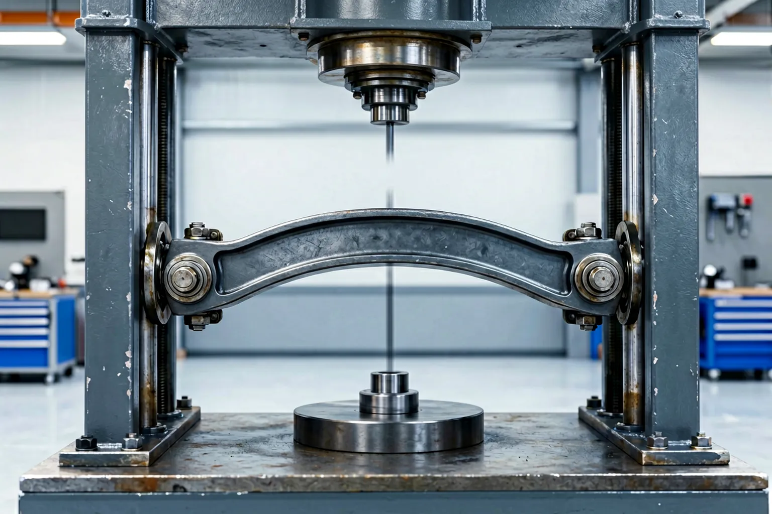
Engineering concept illustration of controlled camber correction on a new leaf spring. Not a customer-site photograph or performance claim. The target remains the drawing-defined arc; tooling, force, supports and acceptance limits require sample trials.
Define the Leaf Spring Family and Supply State
| Workpiece Family or State | Main Difference | Route on This Page |
|---|---|---|
| Equal-thickness single leaf | Relatively uniform section, but eye and hole features affect stiffness | Individual-leaf measurement and correction |
| Master leaf with rolled eyes | Eye axes and eye-to-center relationship are functional | Protected eye support and datum contract |
| Parabolic or tapered leaf | Section stiffness varies along the length | Profiled support and bounded local force |
| Assembled multi-leaf pack | Interleaf friction, clamps and center bolt affect response | Free-arch check plus assembly load test |
| Hot leaf before quench | Camber is being formed as part of the thermal process | Hot-forming/quench tooling, not final cold correction |
| Tempered leaf before finishing | Only controlled final camber or side-bend adjustment | Primary correction candidate after qualification |
| Shot-peened or coated leaf | Surface treatment must remain protected | Contact review and possible downstream reprocessing |
| Used, sagged or cracked vehicle spring | Fatigue history and service damage unknown | Outside this new-manufacturing solution |
Public manufacturing routes from Morita, Nakano Spring, Canara Workshops and Jones Springs place camber forming within or near the heat-treatment sequence, followed by finishing, assembly and testing. That supports a manufacturing correction process — it does not make one temperature, hardness or force recipe universal.
Understand Where Shape Error Enters the Process
Hot Camber Forming and Quenching
The heated leaf can be formed against a preset camber tool and quenched in that condition. Tool setup, part location, temperature distribution and quench behavior all shape the released arc. A problem created at this stage should first trigger a forming and heat-treatment review, not a correction press.
Tempering and Residual-Stress Redistribution
Heat treatment changes strength and redistributes stress. A leaf that matches the tool under load can move after unloading or tempering — so correction needs a released measurement, never only an in-press position.
Eye Rolling, Hole Making and Taper Forming
Rolled eyes, center holes, end features and tapered sections create stiffness transitions — and provide functional references that poor force placement can distort.
Shot Peening, Handling and Assembly
Shot peening is commonly applied to the tension side to improve fatigue performance. Handling, clamps, center bolts and interleaf contact can change the apparent free shape. Where correction is proposed after peening, the customer process owner decides whether repeat peening or additional inspection is required.
Separate Camber, Side Bend and Loaded Shape
Free Camber
Free camber is the unloaded arc or height defined by the drawing and inspection method, measured from specified eye, end or fixture datums. It is not the same as making the leaf flat.
Side Bend
Side bend is lateral deviation from the specified longitudinal plane, needing a separate viewing direction and measurement track from camber. A press setup that changes vertical camber may not correct lateral bow at all.
Twist and Eye Relationship
Twist, eye-axis parallelism and eye-to-center alignment may be drawing characteristics. They stay customer-defined fields until the datum, section and gauge method are supplied; no universal limit is assigned here.
Loaded Height and Load-Deflection
An assembled pack changes shape under load. Loaded height, rate and permanent set are functional test outputs, not substitutes for released geometry — a spring can pass free camber and fail a load test, or the reverse.
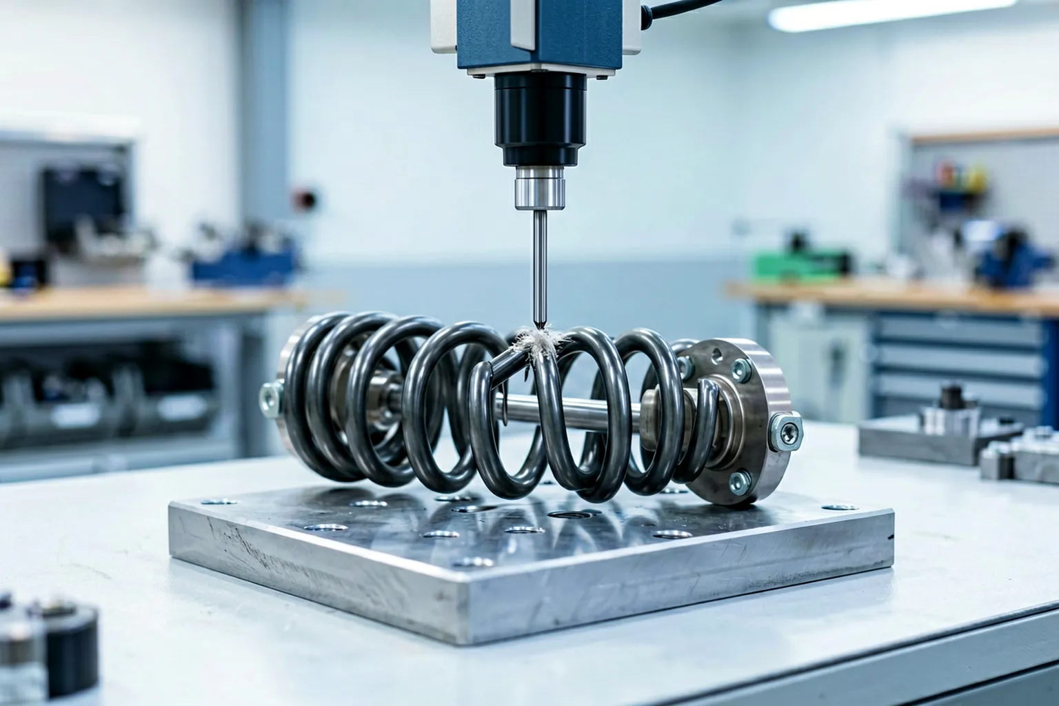
Engineering concept illustration of released camber measurement with protected eye supports and independent sensors. The image shows measurement logic only; actual datums, stabilization time and gauge correlation come from the controlled drawing.
Build the Datum and Measurement Contract
The measurement plan defines:
- leaf family, drawing revision and traceability;
- material, hardness, heat-treatment and surface-treatment state;
- overall length, width, thickness and taper profile;
- eye diameter, eye-axis relationship and center-hole location;
- free-camber definition, chord or datum line, measurement stations;
- side-bend and any twist measurement method;
- support positions, contact width, pad material and restraint force;
- tension side, shot-peened zones, coatings and protected surfaces;
- cleaning, temperature and stabilization condition;
- repeatability after complete release and repositioning;
- assembly condition, specified test load and load-deflection method.
The drawing decides whether eye centers, end lands, a master template or another fixture establishes the datum. Never adopt the easiest support points without checking their functional meaning.
Classify the Condition Before Applying Force
| Observed Condition | Possible Cause | Required Route |
|---|---|---|
| Uniform camber offset along the leaf | Hot-forming tool, quench or temper response | Process review plus bounded camber correction |
| Local high or low region near a transition | Taper, eye or hole stiffness change | Profiled support and feature-aware local correction |
| Lateral bow with acceptable camber | Handling, forming or asymmetric restraint | Dedicated side-bend setup |
| Camber changes after release | Springback, unstable support or insufficient stabilization | Measure-correct-release loop and recipe review |
| Eye relationship out while arc passes | Eye-forming or datum error | Eye-specific disposition; do not press the arc blindly |
| Free shape passes but load test fails | Material, heat treatment, thickness, assembly or set issue | Quality and process review beyond geometry correction |
| Dents, cracks, decarburization or severe surface damage | Material or process defect | Quality disposition before correction |
| Used spring has sag or unknown service history | Fatigue or overload history | Excluded from new-part correction scope |
Protect Functional and Fatigue-Critical Areas
Default Protected or Review Zones
- rolled eyes, eye edges and installed bushings;
- center hole, center bolt seat, clamps and rebound clips;
- tapered or parabolic thickness transitions;
- shot-peened tension surface and finished edges;
- coated, painted or corrosion-protected surfaces;
- stamps, traceability marks and inspection points;
- cracked, nicked, overheated, decarburized or corroded areas.
Potentially Approved Contact Zones
- broad lands identified on the drawing or sample fixture plan;
- replaceable radiused pads matched to the leaf width and arc;
- areas receiving later finishing where the process allows it;
- support zones proven not to mark or locally flatten the spring.
A soft pad does not prove zero damage. Contact pressure, sliding, pickup, local flattening and residual marks must be checked on representative samples.
Use a Released Closed-Loop Correction Process
- Identify the leaf family, drawing revision and process state.
- Confirm the part is a new manufacturing workpiece without cracks or disqualifying damage.
- Clean and stabilize it under the specified condition.
- Locate the approved eye, end or fixture datums without over-clamping.
- Measure free camber, side bend and any drawing-defined secondary characteristics.
- Classify the error; select an approved support span, contact zone and correction direction.
- Apply one bounded press correction while monitoring force and displacement.
- Completely unload the leaf and allow the specified recovery period.
- Remeasure from the same datums.
- Repeat only within correction-count, no-progress, reverse-correction and surface-risk limits.
- Complete visual, dimensional, hardness, crack or other required inspection.
- For a spring pack, assemble and perform the specified setting, scragging or load test.
- Store before/after geometry, force-displacement, iterations and final disposition.
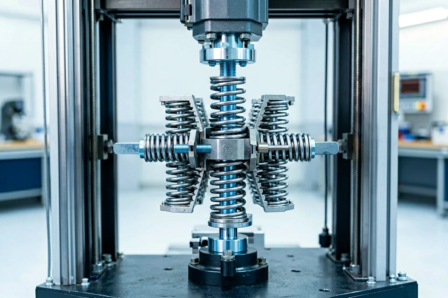
Engineering concept illustration of a multi-leaf pack in a controlled load-verification station — not a delivered-machine photograph. Load points, supports, preload, cycles and acceptance bands require the customer test specification.
Select the Right Correction Architecture
Controlled Press Camber Correction
A hydraulic or servo press with adjustable reactions is the strongest evidenced route for minor final camber correction. The machine preserves the intentional arc and controls springback through repeated released measurement.
Dedicated Side-Bend Correction
Lateral bow may need a horizontal load path, edge supports or a reoriented fixture. It is not the same axis as camber correction and should not be treated as one.
Hot Camber and Quench Tooling
Where the required shape change belongs in hot forming, the correct solution is an integrated camber-forming and quench fixture — a different process window from cold final correction after tempering.
Roller Straightening
Continuous roller straightening is designed for workpieces whose target is a straight longitudinal axis. A finished leaf spring has a designed arc and variable features, so roller straightening is not the default choice — the selection boundary between press and roller routes decides against it here.
Verify Individual Leaves and Assembled Packs Separately
Individual Leaf Release Checks
- free camber or arc at the specified datum and stations;
- side bend and any drawing-defined twist;
- eye diameter, eye-axis relationship and center-hole position;
- width, thickness, taper and local profile after correction;
- contact marks, edge condition and surface-treatment integrity;
- hardness, crack or other NDT checks when required.
Assembled Spring Pack Release Checks
- assembly free arch and left/right relationship where applicable;
- center bolt, clamps, clips and eye/bushing condition;
- the specified setting or scragging sequence;
- loaded height, load-deflection or spring-rate result;
- permanent set after complete release;
- final visual, dimensional and traceability records.
Canara Workshops publicly describes camber correction, hydraulic side-bend correction, assembly arch correction and repeated scragging in its production route; Nakano and Morita show final load testing within leaf-spring manufacture. These sources establish the need for separate geometry and functional gates — the customer’s drawing controls the actual sequence and limits.
Configure the Cell Around the Qualified Family
| Cell Function | Leaf-Spring Requirement |
|---|---|
| Identification | Leaf family, drawing, material, heat treatment, surface state, traceability |
| Handling | Width-supporting transfer protecting eyes, edges and shot-peened surfaces |
| Measurement | Released camber, side bend, eye/center relationship, optional twist |
| Classification | Global camber offset, local arc error, lateral bow, datum error, springback |
| Correction | Adjustable press supports with bounded force/displacement; separate side-bend route |
| Protection | Eyes, center hole, taper transitions, tension surface, coating, traceability marks |
| Verification | Released geometry plus assembly setting/load test where specified |
| Data | Before/after shape, recipe, force-displacement, iterations, inspection, disposition |
Proposal Inputs to Prepare
Send the following before equipment selection:
- controlled leaf and assembly drawings;
- conventional, master, parabolic and pack family list;
- material, heat-treatment, hardness and shot-peening route;
- correction stage and downstream finishing sequence;
- free-camber, side-bend, twist and eye-relationship definitions;
- approved datum, support and contact maps;
- representative incoming shape measurements;
- allowed correction count, surface marks and rejection criteria;
- required hardness, crack or other NDT inspection;
- pack assembly, setting, scragging and load-test specification;
- takt, loading, reporting and traceability interfaces;
- representative good, marginal and reject samples.
Sample-Test Acceptance Before Production Release
The trial should span leaf family, length, width, taper, heat-treatment state, incoming camber and side-bend envelope. It verifies fixture repeatability, datum correlation, force-displacement response, springback, iteration limits, eye and surface protection, released geometry and assembly load behavior. Freeze the test matrix and evidence package before production release.
Engineering Boundary
This solution covers controlled shape correction of new leaf springs during manufacture. It does not certify a used spring for continued service, restore fatigue life, repair cracks, guarantee vehicle ride height, convert one load rating to another, or replace heat-treatment, shot-peening and final load-test controls.
Force, support span, contact geometry, accuracy, cycle time, recovery period and correction count are proposal outputs. They come from drawings, process state, samples and the customer’s gauge — never from a generic competitor specification. Send the leaf-family table and supporting data through the contact page, and a proposed measurement contract, correction architecture, sample-test matrix and equipment configuration will come back for review.
Related Reading
See also: Automotive Parts Straightening, Chassis System Straightening.