
The straightness of a connecting rod sleeve — the extension bar of a power-fastening system — feeds directly into concentricity and running stability of the tool. This page works through the engineering of straightening slender sleeves at 6.35 mm diameter and 200 mm length: deformation control at an extreme length-to-diameter ratio, automated bulk feeding with arbitrary placement and automatic orientation, and servo-driven precision correction. The goal is to show how a customized fully automatic straightener reconciles unmanned high-efficiency loading with a strict 0.2 mm straightness tolerance.
What a Connecting Rod Sleeve Is
A connecting rod sleeve — commonly called an extension bar or bit holder — extends the reach of fastening tools such as electric screwdrivers and impact wrenches. One end carries a drive shank (typically a 1/4-inch hex), the other end the output socket or bit holder. The most common diameter is 6.35 mm (1/4 inch), and because these tools work in deep or narrow spaces, lengths of 200 mm and more are routine. The engine connecting rod itself is a different workpiece entirely, covered in the connecting rod straightening solution.
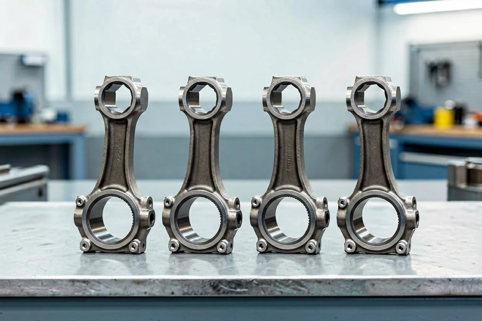
Where the Sleeve Works
Connecting rod sleeves serve industrial assembly and automotive repair fastening tasks, and each application brings its own requirements:
- Automated assembly lines demand extreme straightness so that pneumatic and electric screwdrivers do not wobble at high speed — wobble damages screws and workpiece surfaces.
- Deep-hole and narrow-space work requires high torque transmission and strong surface wear resistance; the heat treatment that delivers both inevitably distorts the part.
Every scenario shares a hard requirement for sleeve straightness (concentricity). A bent rod spinning at speed generates violent centrifugal vibration, causing tool detachment or fastening failure.
Structural Features
- Extreme L/D ratio. At 6.35 mm diameter and 200 mm length, the ratio exceeds 31:1 — a highly flexible, easily deformed slender shaft.
- Asymmetrical ends. Solid hex shank on one end, hollow socket head on the other: the workpiece has a distinct polarity or direction.
- High hardness and elasticity. After heat treatment the sleeve carries high yield strength and shows significant elastic springback during straightening.
Key Characteristics and Technical Parameters
- High-precision transmission: straightness (runout) after correction must hold within 0.2 mm.
- Torsional fatigue resistance: the material must keep its torsional properties, so the straightening process cannot induce surface micro-cracks.
- Mass production: as a high-volume industrial consumable, the per-piece automation cycle must be very fast.
| Item | Parameter Range | Notes |
|---|---|---|
| Workpiece diameter | Ø6.35 mm | Standard 1/4-inch spec |
| Workpiece length | 200 mm | Slender shaft, high L/D ratio |
| Initial bend | 0.5–1.5 mm | Natural distortion after heat treatment |
| Target straightness | ≤0.2 mm | Strict requirement to prevent tool wobble |
| Loading method | Arbitrary placement, auto-orientation | Core customized feature of this equipment class |
Why the Conventional Process Fails on These Parts
Heat-treated slender sleeves expose the structural weaknesses of manual and semi-automatic straightening:
| Pain Point | Specific Issue | Impact |
|---|---|---|
| Extremely time-consuming loading | Traditional feeders require workers to align every part in the same direction by hand | Massive labor waste; production pace collapses |
| Fragile slender shafts | A 6.35 mm rod is easily snapped or permanently over-bent by uncontrolled hammering or heavy presses | High scrap rates and material cost loss |
| Inefficient inspection | Workers slowly roll the part on V-blocks with a dial indicator to find the high point | Precision varies by operator; mass-production consistency impossible |
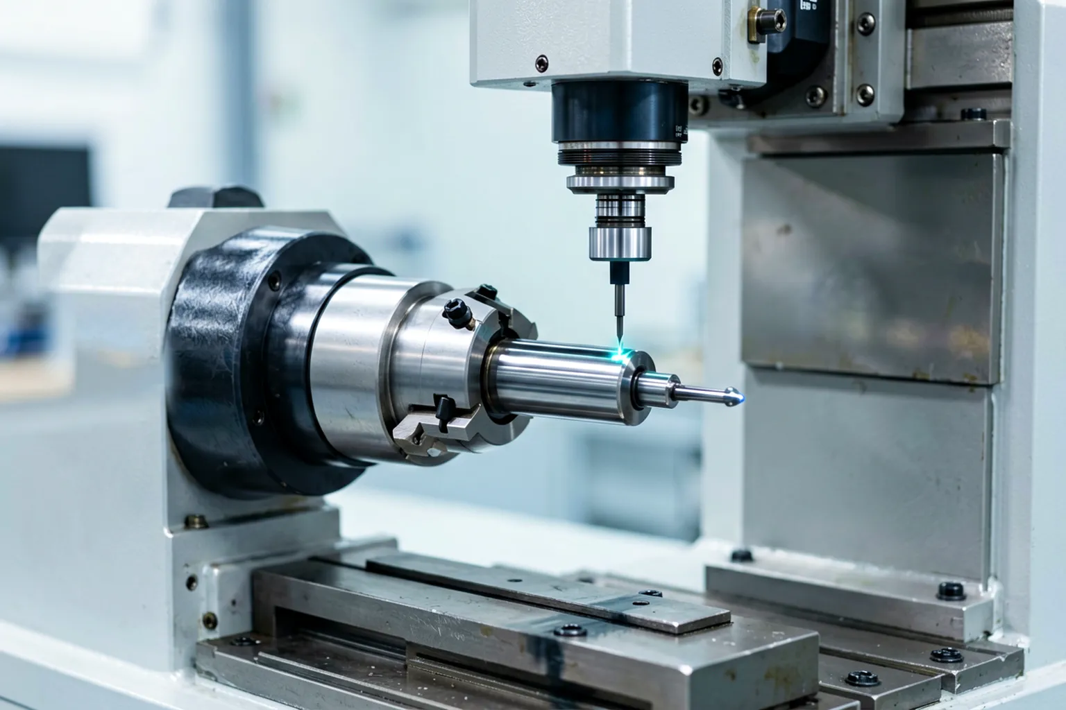
Engineering concept illustration of automated runout measurement on a slender sleeve — the step that replaces operator rolling on V-blocks.
What a Customized Automatic Straightener Changes
| Comparison Dimension | Semi-Auto Straightener | Customized Auto Straightener | Improvement |
|---|---|---|---|
| Loading method | Manual alignment | Random bulk loading, machine auto-orients | True unmanned loading; hands entirely free |
| Straightness | ±0.3 mm | ≤0.2 mm | Consistently stable precision, zero wobble |
| Efficiency | 40–60 s/piece | 10–15 s/piece | Cycle time cut by roughly two-thirds to three-quarters |
| Defect rate | Typical of manual loading | Reduced after commissioning | Micron-level servo pressing eliminates breakage |
Two capabilities carry the improvement:
- Smart orientation recognition. A mechanical flipping-and-sorting mechanism: however the operator dumps sleeves into the hopper, the machine identifies head from tail so that every part reaches the straightening station facing the correct direction.
- Flexible precision straightening. A servo-driven ram with closed-loop force and displacement control, built to absorb the elastic springback of a 6.35 mm slender shaft.
The Automated Straightening Process, Step by Step
The cell completes the job in six fully automated steps, from bulk dumping to discharge of qualified parts. Steps 02 and 05 — auto orientation and servo press straightening — are where the precision of high-L/D parts and the bottleneck of manual loading are both conquered.
| # | Process | Core Mechanism | Time | Precision / Target |
|---|---|---|---|---|
| 01 | Bulk loading & elevating | High-capacity step feeder | Continuous | Allows completely random placement |
| 02 | Auto recognition & orientation | Custom posture ID and flip track | 2 s | Ensures uniform loading direction |
| 03 | Auto feeding & clamping | Pneumatic arm and rotary centers | 2 s | Stable support for the 6.35 mm rod |
| 04 | Rapid runout scanning | High-precision displacement sensor | 3 s | Accurately captures the bend high point |
| 05 | Precision press straightening | Servo ram system | 5–8 s | Straightness ≤0.2 mm |
| 06 | Final check & unloading | Sorting discharge chute | 1 s | Automatically isolates unqualified parts |
Steps 1–2: Arbitrary Placement and Auto Orientation
Purpose: eliminate manual sorting and achieve fully automated, directionally correct feeding of bulk sleeves.
- Operators dump boxes of sleeves straight into the high-capacity hopper without any attention to head or tail direction.
- The elevator feeds parts individually into the recognition track. Using the physical differences in outer diameter and center of gravity between the two ends (or optical sensing where required), the recognition mechanism determines each workpiece’s posture.
- Reversed parts drop into a purpose-built flipping chute that turns them around, so every piece entering the straightening station has its drive end facing the same fixed side.
Steps 4–5: Scanning and Servo Precision Straightening
Purpose: measure the overall bend of the 200 mm shaft and correct it inside the 0.2 mm tolerance.
- For a workpiece only 6.35 mm in diameter, ultra-low-friction support mechanisms prevent secondary deformation during rotation.
- Sensors scan the bending profile in real time, and the control system computes the microscopic reverse deformation required.
- Micron-level servo pressing: rather than an impact-style hydraulic press, a servo motor applies pressure through a slow, precisely controlled displacement. A multi-step approximation algorithm works through elastic springback without damaging the surface, locking straightness within 0.2 mm.
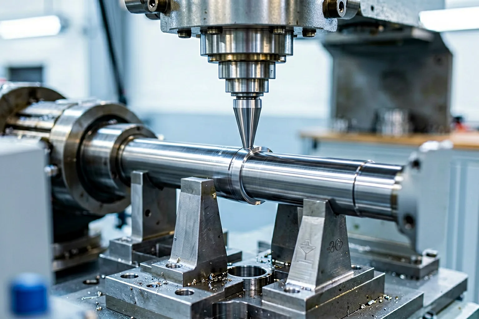
Engineering concept illustration of localized correction on a slender sleeve — contact stays on the shank, away from the hollow socket end.
The Two Hard Problems and Their Solutions
Asymmetrical Ends Cause Auto-Loading Jams
Problem: the sleeve is not a standard smooth shaft — one end is larger than the other. Parts arriving in random directions make clamping fail or send sensors crashing into the workpiece.
Solution: a sorting track built on gravity eccentricity and mechanical profile limits. Without complex robotic vision picking, pure mechanical ingenuity corrects direction instantly as each part slides down — cost-effective, extremely stable, and it eliminates loading jams entirely.
Extreme Fragility at 31:1 L/D
Problem: a 6.35 × 200 mm workpiece behaves like a long chopstick. Slightly too much downward pressure bends it into a V and ruins the part.
Solution: an adaptive springback compensation algorithm designed for slender rods. The ram’s first press uses a conservative force to learn the true springback coefficient of that material batch, then applies micronically precise corrective presses — removing the risk of over-bend scrap.
A Manufacturing Case
Customer Background
A well-known OEM manufacturer of hardware tools and fasteners, exporting heavily to Europe and America, with products widespread in professional-grade power tool accessories.
The Challenge
- An order for millions of connecting rod sleeves at Ø6.35 mm × L200 mm, with a strict 0.2 mm straightness requirement.
- Legacy equipment required operators to identify the direction of each piece and place it into the feed chute manually — at this volume, manual sorting became the bottleneck.
- Heavy labor dependence dropped efficiency on night shifts, and backward-inserted parts caused frequent equipment crashes.
The Configuration
| Item | Parameters / Configuration |
|---|---|
| Workpiece | Connecting rod sleeve (extension bar) |
| Specification | Ø6.35 mm × L200 mm |
| Core equipment | Fully automatic servo straightener with auto-orientation |
| Feeding system | High-capacity step feeder + smart flipping track |
| Precision target | Straightness ≤0.2 mm |
Reported Results
- Labor freed. Operators moved from “sorters” to “loaders” — dumping a basket of parts into the hopper every half hour. One operator now manages five machines simultaneously.
- Yield up. Automatic orientation and micron-level servo straightening removed human error (backward loading, heavy pressing); first-pass yield stabilized at a high level (project-reported).
- Precision locked. Fully automated inspection and sorting verified every part against the 0.2 mm limit before release, supporting the brand’s reputation in the international tool market.
Frequently Asked Questions
What is the success rate of arbitrary-placement auto-orientation — will reversed parts slip through?
With physical limits and center-of-gravity recognition tracks, parts are oriented automatically. A defective part with severe burrs or abnormal dimensions that cannot be flipped is diverted to a reject chute — a reversed workpiece never reaches the core straightening zone to cause a crash.
The workpiece is so slender — why not use a multi-roll pass-through straightener?
Multi-roll straighteners are fast, but a connecting rod sleeve carries a hex shank on one end and a hollow socket on the other. Multi-roll machines cannot process these unequal-diameter, asymmetrical ends, and continuous rolling might distort the roundness of the socket wall. Servo press straightening — point scanning plus localized pressing — is the viable route.
Can the machine handle other sleeve lengths?
Yes. Sensor spacing, center distance and discharge chutes are modular and adjustable: change the mechanical limits, call up the corresponding workpiece recipe on the HMI, and the same cell covers length specifications from 100 mm and 150 mm up to 300 mm.
How is the 0.2 mm result verified on every part?
Step 06 of the cycle re-measures each released part at the defined stations before discharge, and the sorting chute isolates anything outside the limit. Verification therefore rides inside the production cycle rather than depending on sampled manual checks — which is what keeps a consumable-class part economical to inspect at full volume.
For the larger engine-family workpiece on the same name, see the connecting rod straightening solution; for enquiries on sleeve-type parts, drawings and sample lots go through the contact page.