
A crankshaft is a multi-axis, fatigue-critical component — not a conventional round shaft. Its main bearing journals are meant to share one common rotation axis, while every connecting-rod crankpin deliberately orbits around that axis at an offset. Webs, counterweights, thrust faces, fillet radii, oil holes, nose features and the flywheel flange each shape how the part can be measured and which load path is safe.
Before any machine is selected, a workable crankshaft straightening solution has to answer five questions:
- Is this a production crankshaft, a remanufacturing part, or a small-engine repair job?
- Which main-journal axis and which support condition define the bend map?
- Is the deviation a correctable global bend, local journal form error, a grinding-stock problem, or a crack/damage condition?
- Which pressure, roll-straightening or peening route is approved for this material at this stage?
- How will released geometry, fillet integrity, grinding allowance and final balance be verified?
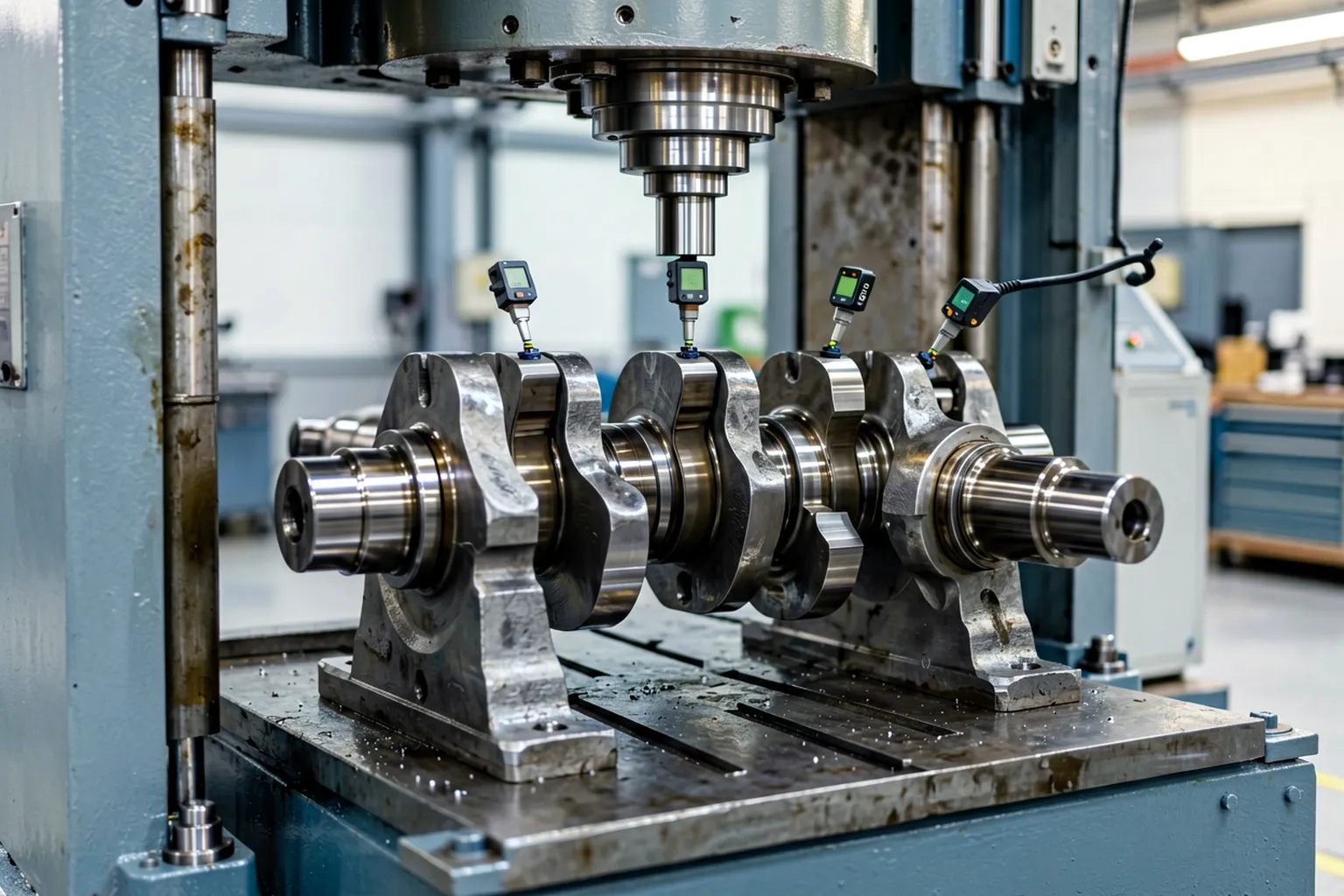
Engineering concept illustration: a multi-throw crankshaft supported and measured during a controlled correction study. Not a customer-site photograph. Real contact zones, force limits and machine architecture require the drawing and representative sample tests.
Crankshaft Straightening Is Several Markets, Not One
Search results for crankshaft straightening machine mix several distinct intents on one page: small-engine repair tools, workshop hydraulic presses, large crankshaft repair equipment, and high-production deep-rolling or roll-straightening systems. These do not collapse into one generic machine offer.
| Crankshaft Family | Typical Context | Engineering Route |
|---|---|---|
| Forged automotive crankshaft | Controlled production between machining operations | Automated measurement plus a validated pressure or roll-straightening process |
| Large diesel, marine or industrial crankshaft | New production or specialized repair | Heavy handling, multiple supports, project-specific pressure/rolling route |
| Remanufacturing crankshaft | Wear, heat, crash or bearing-failure history | Inspection, grinding-stock and repair decision before any straightening |
| Small vertical-shaft engine crank | Compact repair-tool market | A separate product, fixturing and safety envelope |
| Built-up or pressed crankshaft | Assembled webs, pins and interference fits | Assembly alignment process; not a one-piece forged-crank recipe |
| Cast or nodular-iron crankshaft | Material-specific fatigue and crack behavior | Metallurgical approval and a restricted correction study |
This page deals with one-piece industrial and automotive crankshafts. A lawn-equipment straightener or a built-up motorcycle crank needs a different solution entirely.
Map the Anatomy and the Datum Chain
The technical proposal should list every functional feature:
- all main bearing journals, with their numbering;
- connecting-rod crankpins, stroke and angular phase;
- webs and counterweights;
- front nose, timing, keyway, spline or gear features;
- rear flange, pilot bore and flywheel interface;
- thrust faces and the axial datum;
- main- and pin-journal fillet radii;
- oil holes, cross-drillings and internal passages;
- hardened or deep-rolled regions;
- balance holes, milled pads or added balance features;
- centers or temporary process datums;
- grinding stock, journal by journal and stage by stage.
The main-journal common axis normally decides the global bend question. Crankpins are eccentric on purpose and must be judged relative to the main axis, stroke and phase — a crankpin’s raw radial motion is not, by itself, evidence of a bent shaft.
Freeze the Manufacturing or Repair Stage
After Forging and Rough Machining
Scale, stock variation and unfinished datum features may all be present. Correction can help downstream machining, but the measurement system must tell stock variation apart from genuine axis displacement.
After Main- and Pin-Journal Pre-Machining
Functional journal tracks and process datums exist while grinding allowance remains. Established heavy-machinery literature (Hegenscheidt) places deep rolling and roll straightening after pre-machining, with main-bearing TIR measured before the correction calculation — proof that process stage and stock plan are inseparable.
After Heat Treatment or Surface Hardening
Residual stress, hardness and springback all shift. A force/displacement recipe learned on a soft blank cannot simply be carried over to a hardened crankshaft, and crack risk plus post-process inspection become explicit acceptance gates.
After Fillet Deep Rolling
Deep rolling exists to put compressive residual stress into highly loaded fillets. A later correction operation must not undo that condition or impose an unvalidated strain path. Pressure contact on the fillet is out unless the crankshaft designer approves a dedicated process.
Before Final Grinding
Straightening can reduce the stock needed to generate a common main-journal axis — but the outgoing map must prove every journal still carries adequate grinding allowance.
After Final Grinding
Journal diameter, roundness, finish, fillet geometry and thrust faces are now functional. Contact rules tighten, and a regrind/repair/reject route may be safer than further pressure correction.
Service or Remanufacturing Return
Heat damage, bearing seizure, scoring, cracks, previous grinding, welding, plating or prior straightening all change the risk. Force should not be applied before a repair history and inspection record exist.
| Stage | Main Opportunity | Main Risk | Required Evidence |
|---|---|---|---|
| Rough forging | Reduce machining imbalance | Stock variation masks geometry | Qualified process datums and a stock map |
| Pre-machined | Multi-journal bend map available | Wrong support reference | Main-journal TIR and grinding allowance |
| Heat-treated | Correct heat-treatment distortion | Springback and crack initiation | Material/hardness plus force-displacement trials |
| Deep-rolled | Coordinate runout with fillet-strength process | Damage to the compressive fillet condition | Process-owner approval and fillet protection |
| Finish-ground | Salvage within final geometry | Surface/form damage and lost stock | Full journal/fillet inspection and repair limits |
| Service return | Recover a repairable component | Hidden fatigue, heat or prior-repair damage | NDT, history, stock and disposition rules |
Keep Main Journals and Offset Crankpins on Separate Tracks
Production gauging practice (Marposs documents crankshaft gauging of this type) measures main-journal diameters rotating about the main geometric axis and pin-journal diameters following an orbital path around it. That separation of signals is fundamental, not optional.
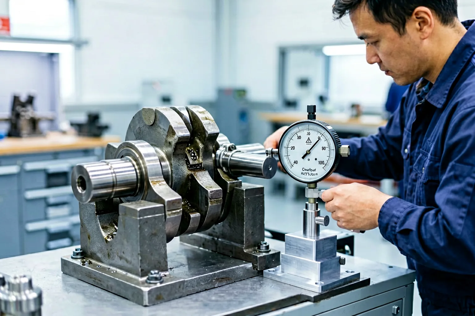
Engineering concept illustration: the main-journal bend map and the offset crankpin geometry need separate measurement tracks. Actual probe locations, rotation model and feature masks follow the drawing and the gauge-correlation plan.
| Measurement Track | What It Establishes | Common Error if Misused |
|---|---|---|
| All main journals | Common-axis runout and the bend map | Local lobing read as global bend |
| Front and rear main journals | Support/reference axis | End damage biasing the whole map |
| Crankpins | Diameter, orbit, stroke and phase relation | Intentional eccentricity read as runout |
| Thrust faces | Axial location and face runout | Burrs or local wear dominating the reading |
| Front nose and rear flange | Connected-component relationship | Feature error treated as shaft bend |
| Journal roundness/cylindricity | Local form | A low TIR hiding local form error |
| Fillet and oil-hole regions | Structural and surface condition | A fatigue-critical defect missed |
| Balance correction planes | Mass-axis condition | Balance mistaken for geometric straightness |
Commercial crankshaft metrology systems (Nidec’s measuring systems grade journal and pin outside diameters separately; Marposs supports final and inter-operational dimensional, geometric and non-destructive measurement) point to the same transferable lesson: not a competitor accuracy figure, but the necessity of a drawing-based, multi-characteristic inspection plan.
Choose the Support Reference Deliberately
Crankshaft runout may be measured:
- between qualified centers;
- on end main journals;
- on selected V-rollers;
- in bearing-equivalent supports;
- in a grinding-machine or dedicated gauge setup.
Equipment literature (Hegenscheidt again) allows runout measurement referenced to centers or V-blocks — and these setups do not automatically agree. The solution must define:
- physical support journals and their coordinates;
- center condition and qualification method;
- journal roundness compensation;
- axial restraint and permitted movement;
- crank angle and angular indexing;
- gravity sag compensation for large crankshafts;
- sensor force and feature masks;
- released-state repeatability;
- correlation to the grinder and the customer gauge.
Datums must not change midway through a correction loop without an established transformation and correlation study behind the switch.
Pressure, Roll Straightening and Peening Are Different Animals
Controlled Pressure Straightening
A press applies a localized three-point or constrained load at an approved main-journal region. Heavy-duty repair equipment on the market (Gleason’s crankshaft line is one example) shows the pattern: supports, overhead hold-downs and a movable ram localizing the work around a chosen journal. Any specific competitor layout is market context, never a specification for your part.
Pressure straightening requires:
- a verified global-bend diagnosis;
- an approved load path through journals and webs;
- broad, radiused contact tooling;
- force and displacement ceilings;
- springback characterization;
- complete unloading before acceptance;
- post-correction crack and surface checks.
Roll Straightening
The Hegenscheidt process combines angle-dependent deep rolling, main-bearing TIR measurement and roll straightening — a production technology tied to fillet treatment and pre-grind geometry. It is not a generic multi-roll bar straightener and must not be sold as one.
Peening
Repair-market sources also describe peening methods. Peening redistributes local residual stress and demands its own qualified work instruction, operator controls, surface rules and inspection. It is not an automatic substitute for pressure straightening, and no universal peening recipe is claimed here.
| Method | Potential Fit | Primary Control | Do Not Assume |
|---|---|---|---|
| Pressure straightening | Approved bare crankshaft with a safe load path | Force, displacement, support span, released TIR | Finished fillets or journals tolerate contact |
| Roll straightening | Production process integrated with journal/fillet operations | Angle-dependent rolling and the main-journal map | One tooling set fits every crank family |
| Peening | Specialist repair method | Location, intensity, residual stress, surface inspection | Hammering is inherently safe or repeatable |
| Grinding | Local form/diameter and limited eccentricity within stock | Journal geometry and stock removal | Grinding can remove every global bend |
| Replacement/rejection | Crack, burn, insufficient stock or unsafe load path | Engineering disposition | Every bent crankshaft is repairable |
Build a Protected Contact Map
Default No-Press and No-Support Zones
- main- and pin-journal fillet radii;
- oil holes and cross-drillings;
- offset crankpins, unless a dedicated route approves them;
- thrust faces and finished flange faces;
- keyways, splines, threads and timing features;
- balance holes and local mass-correction features;
- sharp web transitions and thin counterweight edges;
- deep-rolled, induction-hardened, nitrided, welded, plated or repaired regions;
- cracked, burned, scored or heat-affected surfaces;
- finished journals without protected-tooling approval.
Potentially Approved Zones
- rough or semi-finished main-journal lands with adequate stock;
- process collars or sacrificial extensions;
- designer-approved web/journal load paths;
- dedicated rolling contact locations defined by the manufacturing process.
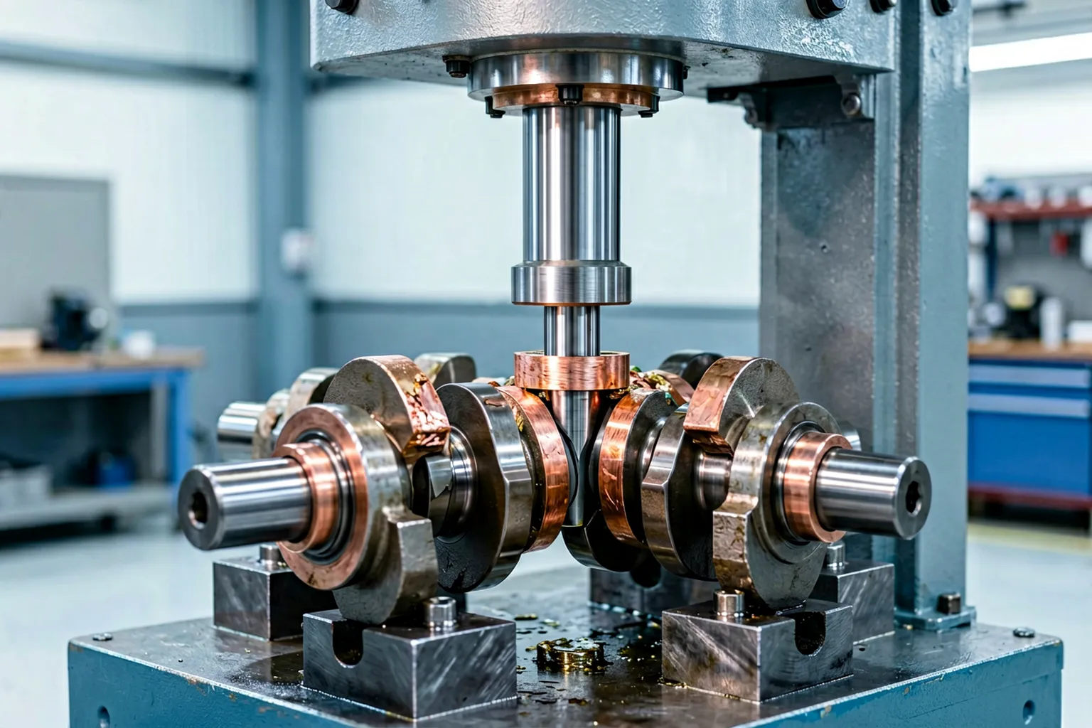
Engineering concept illustration: correction confined to an approved main-journal load path while fillets, oil holes, crankpins and thrust faces stay protected. The image authorizes nothing for a real part.
Store the safe contact map against part number and drawing revision. A journal that was fair game before grinding may be a protected final surface one operation later.
Manage Springback and Cross-Coupling
Correcting one main journal elastically reshapes the adjacent webs and journals. The process must work from the complete main-journal bend map rather than chasing a single indicator peak.
For every correction step:
- rotate and measure all controlled main journals;
- separate local form from center displacement;
- identify the correction coordinate and crank angle;
- apply a validated incremental load;
- record force and displacement;
- unload fully;
- rotate and remeasure the complete map;
- check adjacent crankpins, thrust/flange and protected surfaces;
- stop on abnormal stiffness, non-repeatability or any inspection indication.
Loaded displacement is never the finished result. Only a released, repeated map shows whether springback was compensated safely.
Straightening vs Grinding
Grinding generates journal diameter, roundness, cylindricity and finish, and it can remove limited eccentricity while stock remains. It cannot be assumed to restore a common main-journal axis when the stock removal that would require violates size, fillet or hardness limits.
The decision needs a journal-by-journal stock map:
- incoming diameter and runout;
- minimum finished size;
- remaining hard layer or repair coating;
- permitted undersize or repair class;
- fillet and thrust-face geometry;
- grinder support and datum setup;
- expected stock after released straightening.
In-process grinding gauges (Marposs publishes such systems for crankshaft grinding) confirm that main and pin journal diameters have distinct motion and measurement requirements. Plan straightening and grinding as connected but separate operations.
Straightening vs Balancing
Balancing corrects mass distribution relative to defined correction planes — in engine applications often linked to bobweight and rotating/reciprocating mass assumptions. It does not correct main-journal coaxiality, pin-journal form or a bent global axis.
Wherever straightening, grinding, drilling, milling, welding, plating or any material removal happens after balancing, the final balance condition must be re-verified. A crankshaft can pass geometric runout and fail balance — or pass balance with a geometrically displaced main journal.
Crack, Surface and Fatigue-Sensitive Inspection
Hitting a runout target means nothing if correction introduces a harmful indication or damages a fatigue-critical surface. The inspection plan should define:
- pre-cleaning and visual inspection;
- magnetic-particle, eddy-current or another approved NDT route by material and process;
- fillet and oil-hole coverage;
- journal dent, bruise and surface-finish limits;
- grinding-burn or heat-damage inspection;
- hardness and depth checks where required;
- acceptance criteria for prior weld, plating or repair;
- inspection timing before and after correction and grinding;
- engineering disposition for borderline indications.
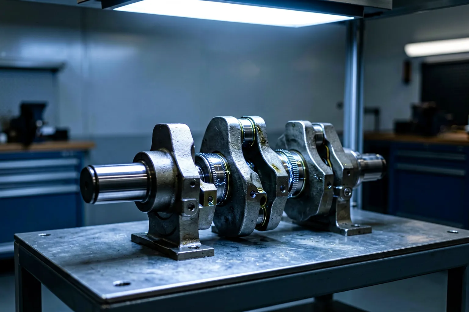
Engineering concept illustration of magnetic particle inspection after correction. Claims about fatigue-strength preservation belong to the validated rolling system that earned them (Hegenscheidt’s process claims, for instance) — they cannot be transferred to a pressure-straightening proposal without independent samples, material approval and fatigue-sensitive validation.
A Closed-Loop Crankshaft Straightening Process
1. Identify the Part
Load the correct recipe from crankshaft number, engine family, material, process stage, drawing revision and repair history.
2. Inspect and Clean
Clean journals and datum surfaces. Inspect oil holes, fillets, journal surfaces, webs, nose and flange. Complete any required pre-process NDT.
3. Qualify the Datum Setup
Verify centers or support journals, axial location, rotation and seating repeatability.
4. Build the Multi-Journal Map
Measure every main journal through rotation. Record pin-journal, thrust, nose and flange characteristics on their own tracks.
5. Classify the Deviation
Separate global bend from journal lobing, taper, grinding-stock error, crankpin phase/stroke error, flange damage, crack, heat distortion or unbalance.
6. Select the Approved Method and Load Path
Choose pressure, rolling, peening, grinding or rejection per the validated part route. Confirm every protected zone.
7. Apply Incremental Correction
Control force, displacement, crank angle and tooling position. Stop on abnormal response.
8. Release and Remeasure
Unload fully and rotate the crankshaft again. Update the complete main-journal map — not just the corrected location.
9. Inspect and Route Downstream
Run post-correction NDT and surface checks, confirm grinding stock, then route to grinding, final gauging, balancing and assembly inspection.
10. Record the Result
Store identity, recipe revision, datum setup, before/after maps, correction coordinates, force-displacement curves, alarms, inspection results and disposition.
What a Crankshaft Straightening Cell Contains
A project-specific system may include:
- an electromechanical or hydraulic correction unit sized by sample testing;
- adjustable main-journal rollers, centers or V-supports;
- servo rotation and crank-angle indexing;
- multiple runout sensors for the main-journal map;
- separate crankpin, thrust, nose and flange measurement modules;
- broad interchangeable press shoes and protected supports;
- automatic keep-out logic for fillets, oil holes and counterweights;
- force/displacement monitoring and springback compensation;
- heavy-part loading, lifting and anti-roll safety;
- recipe control, traceability and quality-data export;
- interfaces to grinding, NDT and balancing records.
The configuration that suits a small automotive crankshaft does not automatically suit a large marine crankshaft or a repair-shop part.
Sample Test and Acceptance Plan
Representative samples should cover:
- smallest and largest crankshaft length, swing, mass and journal diameter;
- different main-journal counts, crankpin strokes and counterweight layouts;
- forged, cast and approved repair conditions;
- rough, pre-machined, heat-treated, deep-rolled and finish-ground stages;
- material and hardness extremes;
- expected incoming bend shapes and crank angles;
- journal form-error samples that should not trigger correction;
- minimum grinding stock;
- approved and prohibited contact zones;
- the force/displacement and springback envelope;
- adjacent-journal cross-coupling;
- main-journal and crankpin gauge correlation;
- pre/post NDT and surface results;
- final grinding and balance verification;
- repeatability and NOK routing.
A structured sample test and acceptance program is what separates feasibility conclusions from FAT, SAT and production capability evidence — apply one before signing off any crankshaft cell.
Data Required for a Technical Proposal
Please provide:
- crankshaft drawing and revision;
- engine/application and crankshaft family;
- one-piece forged/cast or built-up construction;
- material, heat treatment, hardness and fillet treatment;
- current manufacturing or repair stage;
- main-journal, crankpin, thrust, nose and flange dimensions;
- stroke, pin phase and counterweight layout;
- oil-hole and internal-passage map;
- incoming main-journal runout map by angle;
- journal roundness, cylindricity and taper results;
- drawing datums and customer measurement setup;
- approved support/correction zones and prohibited features;
- grinding stock by journal;
- crack, burn, surface and repair acceptance criteria;
- downstream grinding, balancing and assembly sequence;
- report and traceability requirements;
- representative samples for trials.
Frequently Asked Questions
Can a crankshaft be straightened?
Some can. Feasibility depends on material, construction, process stage, bend shape, grinding stock, fillet condition and a safe load path. A crack, heat-damaged journal or insufficient stock may call for repair or rejection instead.
How can you tell if a crankshaft is bent?
Measure all main journals in a qualified support setup and separate local roundness from center displacement. Crankpin orbital motion, thrust-face runout and flange/nose features each need their own track.
Can you press on a crankpin or fillet?
Do not assume so. Crankpins are offset features and fillets are fatigue-critical. The default contact map protects crankpins, fillets, oil holes and finished thrust surfaces unless a dedicated process has been approved.
Is peening better than press straightening?
They are different residual-stress and correction processes. The right route depends on crankshaft design, material, production or repair stage and validated work instructions — neither should be chosen from a generic internet procedure.
Can grinding remove crankshaft bend?
Grinding removes limited eccentricity within the stock allowance and produces final journal form. It cannot safely solve every common-axis error. Decide with a journal-by-journal stock map.
Is crankshaft balancing still required?
Yes, where specified. Straightening corrects geometry; balancing corrects mass distribution. Re-verify balance after any operation that changes geometry or mass.
Should a service crankshaft be inspected for cracks?
Yes, per the material, repair standard and customer requirement. Straightening must never be used to hide a crack, burn, seizure or previous-repair condition.
Build the Solution Around the Main-Journal Axis
A crankshaft straightening solution has to be developed around the actual crank family: main-journal datum, offset crankpin geometry, process stage, protected fillets, safe load path, released bend map, grinding stock and the final inspection sequence. Machine architecture follows evidence from drawings and sample trials — not a generic shaft recipe or a competitor brochure.
Send the crankshaft drawing, process stage, material condition, incoming journal map, grinding allowance, inspection standard and representative samples — through the contact page — and the measurement strategy, pressure or rolling route, tooling map, correction envelope and traceable acceptance plan for the application can be defined from there. For the valvetrain counterpart on the same engine line, see the camshaft straightening solution; for the connecting-rod side of the crank train, the connecting rod straightening solution applies the same released-measurement discipline.