
An engine poppet valve looks like a simple stem with a circular head, but its functional geometry is a set of related features. The stem runs in the guide; the conical face must seat correctly; the head, margin, neck, keeper grooves and tip each carry different manufacturing and contact risks. Material and construction can differ between intake and exhaust valves, too.
For that reason an engine valve straightening machine is never selected from overall length and stem diameter alone. A viable solution answers five questions:
- Is the part a one-piece valve, a welded or bimetallic valve, or a hollow design?
- Which finished or semi-finished stem lands define the datum axis?
- Is the measured error stem bend, head or seat eccentricity, local form error, surface variation or setup error?
- Where can the valve be supported and corrected without marking a functional feature?
- How will the released valve be remeasured and correlated with downstream grinding and final inspection?

Engineering concept illustration of a bare poppet valve in a closed-loop measurement and correction cell. Not a customer-site photograph or performance claim. Actual probes, supports and load points require drawing review and representative sample tests.
Define the Valve Family Before Designing the Cell
This page covers bare poppet valves for internal-combustion engines during controlled production or remanufacturing. Not every part called a valve is the same workpiece:
| Valve or Part Family | Primary Geometry | This Page |
|---|---|---|
| One-piece intake or exhaust poppet valve | Stem, neck, head, face, margin, grooves, tip | Primary scope |
| Friction-welded or bimetallic valve | Different stem and head materials, a joint, possible axis relationship | Project-specific material and joint review |
| Hollow or sodium-filled exhaust valve | Thin-wall or filled internal construction | Separate risk review before any correction |
| Finished service valve removed after engine damage | Possible impact, fatigue, heat or crack damage | Inspection and replacement decision before straightening |
| Hydraulic spool or control valve | Precision lands and bores | Use a spool-specific solution |
| Needle valve or injector component | Small precision conical and cylindrical features | Separate precision-component project |
| Valve guide, seat insert or rocker component | Different function and datum chain | Outside this page |
A production valve distorted after heat treatment is not equivalent to a service valve bent by piston contact. The first may be a controlled manufacturing-correction candidate; the second may carry hidden damage that no straightness value can make acceptable. The neighbouring valvetrain parts follow the same production-versus-repair split — see the rocker arm and camshaft solutions for the pattern.
Map the Functional Features
Before a machine concept is released, the drawing and process plan should identify:
- stem tip and any hardened tip zone;
- keeper or collet grooves;
- plain guide-diameter lands on the stem;
- welded junction where the valve uses more than one material;
- neck and fillet transition;
- valve head and head thickness;
- conical face or seating surface;
- margin and outer head edge;
- coating, nitrided, chrome-plated or specially hardened areas;
- internal hollow or filled region where applicable;
- grinding allowance and final inspection datums.
The approved contact map attaches to the part family and revision. Moving a support a few millimetres can shift it from a plain cylindrical land onto a groove, a transition, a coating boundary or a weld-affected area.
Freeze the Process Stage
ETA Technology publicly positions valve straightening after heat treatment and before later seat-related turning and grinding. That sequence is a useful process-planning reference — not a universal recipe. Each project still needs its own drawing, material state and downstream stock review.
Before Heat Treatment
The valve may be easier to load, but subsequent heat treatment creates new distortion. Straightening here only makes sense when it supports the next operation and does not replace post-heat-treatment inspection.
After Heat Treatment, Before Final Grinding
Usually the most relevant production window: distortion has occurred, yet controlled grinding allowance may remain. Hardness, case depth, material pair and crack sensitivity become mandatory recipe inputs.
After Final Stem, Face or Tip Finishing
Functional surfaces now carry stricter marking and geometry limits. Correction may damage a finished guide diameter, seat face, coating or tip — a sample test must prove both geometry and surface integrity.
Service or Remanufacturing Return
An overheated, impacted, fatigued, burned or cracked valve is not automatically a straightening candidate. The incoming route first evaluates damage history, material condition and replacement policy. A straight valve can still be unsafe or unable to seal.
Build the Datum Chain Around Function
The stem guide diameter is normally the central functional reference, but the inspection setup must state exactly which axial lands and support condition establish that axis. The head and seating face are then evaluated relative to the agreed stem datum.
The measurement plan should separate:
- stem runout at multiple axial sections;
- local stem diameter and form error;
- head runout or wobble relative to the stem axis;
- conical face or seat runout relative to the stem axis;
- tip and groove position where the drawing requires;
- datum repeatability after unloading and reclamping;
- temperature, cleanliness and rotational support effects;
- final correlation with the customer’s gauge or grinding machine.
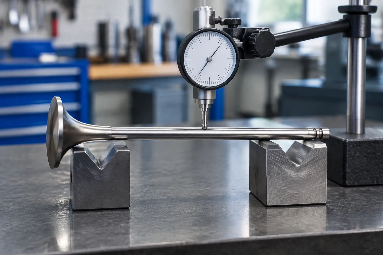
Engineering concept illustration of feature-specific valve measurement — not a prescribed gauge layout. Probe tracks, contact force, support points and datum construction follow the controlled drawing and inspection agreement.
Do Not Call Every Rotating Signal a Bent Stem
| Observed Signal | Possible Cause | Required Decision |
|---|---|---|
| Related phase error across several stem sections | Global stem bend | Candidate for controlled correction after material and contact review |
| One stem section differs while adjacent sections stay stable | Local form, surface damage, deposit or measurement artifact | Inspect the feature; never compute a global bend from one trace |
| Stem runs consistently but head or seat wobbles | Head/face eccentricity, forming error or material-junction axis shift | Route to process engineering; stem pressing may not solve it |
| Signal changes after reclamping | Dirty support, groove contact, roller error or unstable datum | Correct the setup and repeat the measurement |
| Finished surface shows a periodic trace | Grinding, coating or support interaction | Verify form and surface rather than applying more correction |
| High correction demand near a welded junction | Axis mismatch, local stiffness change or joint issue | Stop and review construction and joint quality |
| Valve is straight but fails sealing or leakage inspection | Face, seat, guide, assembly or damage problem | Inspect the complete functional chain |
Marposs describes separate quality checks for guide-diameter straightness and roundness, plus conical-seat runout relative to the guide diameter. That supports feature-specific inspection — it does not prove every observed error can be corrected by the same straightening operation.
Classify the Valve Construction Before Applying Force
One-Piece Valves
A one-piece design still carries local hardness, diameter and section changes. The recipe must account for stem, neck and head rather than assuming a uniform round bar.
Welded or Bimetallic Valves
Different materials and a welded joint create a stiffness transition and an axis relationship that differ from a simple bend. ETA explicitly publishes a limitation for bimetallic valves with axis shift on one of its valve-straightening routes — evidence that joint location and axis shift must be treated as engineering gates, not routine automatic correction.
Hollow or Filled Valves
Internal cavities or fill material change section stiffness and damage consequences. Do not transfer a force window from a solid valve. Construction data and representative section validation precede any approved correction route.
Hardened or Coated Valves
MAHLE publicly describes valve variants with hardened, chrome-plated or nitrided features. Exact construction varies by application, but the engineering implication is consistent: surface condition and hardness belong in the straightening recipe and the acceptance plan.
Create a Protected Contact Map
Default No-Support and No-Press Zones
- keeper grooves and groove shoulders;
- stem tip and hardened tip face;
- neck and fillet transition;
- valve head, margin and outer edge;
- conical face or seating surface;
- welded or friction-welded junction unless specifically approved;
- coated, plated, nitrided or finished gauge surfaces without validated inserts;
- cracked, burned, impact-marked or corroded areas;
- thin-wall or internally hollow regions without construction approval.
Potentially Approved Contact Zones
- plain cylindrical stem lands with sufficient distance from grooves and transitions;
- semi-finished lands that retain downstream grinding stock;
- broad replaceable inserts validated for surface pressure and marking;
- family-specific support positions controlled by axial datum and part revision.
The press point should never simply sit at the highest measured indicator value. The controller must reconcile the bend vector with safe contact zones, support span, local section, material state and springback history.

Engineering concept illustration of two supports and one correction shoe acting only on approved plain stem lands — not a universal fixture. Contact width, insert material, load position and allowable force require sample validation.
Select the Correction Route
Closed-Loop Cold Press Straightening
A suitable automatic cell loads the bare valve, establishes the datum, rotates or scans the part, calculates the correction vector, applies a bounded press stroke, fully releases the load, remeasures. The loop continues only within approved force, displacement, iteration and surface limits. A valve application adds feature-specific probes, short contact windows and stronger material-construction gates to the standard closed-loop sequence.
Correction Before Final Grinding
Where the process plan allows it, retaining controlled stock on the stem or related features reduces finished-surface risk and provides a final geometry operation. The downstream grind must use a compatible datum and must not recreate the error.
Thermal or Specialist Repair Route
Some material states need a qualified thermal or specialist process rather than a standard cold press. That route demands metallurgical approval, temperature control, post-process inspection and its own acceptance evidence — never an automatic option inferred from the workpiece name.
Reject or Replace
Cracks, heat damage, severe impact, unacceptable joint condition, excessive local deformation, insufficient grinding stock or an unapproved hollow construction can make rejection the correct route. A solution provider defines this boundary before machine acceptance.
Use a Released-Part Control Loop
Design the production sequence around the released valve — never the value observed while the press is still loaded.
- Identify the valve family, revision and process stage.
- Clean and load the part on approved stem lands.
- Establish the stem datum and check setup repeatability.
- Measure stem sections; separate head- and face-related signals.
- Classify the error and confirm the requested correction lies inside the approved route.
- Select supports and press point from the protected contact map.
- Apply a bounded correction; record force and displacement.
- Fully unload the valve and allow the defined stabilization period.
- Remeasure the same controlled tracks.
- Accept, make another bounded iteration, or route the part to NOK review.
- Perform required surface, crack, hardness or downstream functional checks.
The springback compensation model must be trained and limited by the specific valve family, material state and contact map — a model borrowed from another part family is a liability, not a head start.
Configure the Production Cell Around the Part Family
| Cell Function | Valve-Specific Requirement |
|---|---|
| Identification | Valve family, revision, intake/exhaust type, material construction, process stage |
| Loading | Manual, bowl, robot or line transfer without head, face, groove or coating damage |
| Datum establishment | Stable rotation or scanning on approved stem lands, with reclamp checks |
| Measurement | Multiple stem sections plus separate head/face tracks where required |
| Correction | Servo-controlled displacement and force inside approved contact windows |
| Tooling | Quick-change, mistake-proof supports and press shoes linked to the recipe |
| Verification | Fully released remeasurement and correlation with downstream gauges |
| Quality routing | Automatic OK, controlled rework, engineering review, hard reject states |
| Traceability | Part family, recipe, initial trace, correction history, final trace, alarms |
Automation level follows production volume, valve-family mix, incoming stability, traceability and changeover requirements — not a competitor’s cycle-time claim.
Validate the Solution With Representative Samples
A sample test contains the real sources of variation, not only easy nominal parts. Include, as applicable:
- minimum and maximum valve geometry within the proposed family;
- intake and exhaust variants;
- material and hardness states;
- one-piece, welded or hollow constructions only when in scope;
- realistic initial bend direction and magnitude;
- coating and finished-surface variants;
- accepted and known-NOK examples;
- repeated loading and reclamping trials;
- downstream grinding or final-gauge correlation.
The acceptance report should state sample count, gauge method, support condition, released-part dwell, initial distribution, final distribution, iterations, force/displacement traces, surface findings, NOK reasons and excluded variants.
What Straightening Does Not Repair
Straightening changes geometry inside a validated material and contact window. It does not automatically repair:
- cracks, fatigue or impact damage;
- a burned valve head or eroded seating face;
- guide wear, seat damage or cylinder-head misalignment;
- a poor weld or bimetallic axis mismatch;
- lost hardness or an unsuitable heat-treatment condition;
- damaged coating, grooves, tip or margin;
- leakage caused by other parts of the valvetrain;
- an unsafe service valve that should be replaced.
This boundary is part of the solution, not a limitation to hide.
Information Needed for an Engine Valve Proposal
Please provide:
- controlled valve drawing and revision;
- intake/exhaust designation and application family;
- overall length, stem diameter, head diameter and critical axial positions;
- material, one-piece/welded/hollow construction and joint location;
- hardness, heat treatment, coating and surface-finish requirements;
- manufacturing or repair stage at straightening;
- current datum, gauge method and runout definitions;
- initial error distribution and target acceptance criteria;
- approved and prohibited contact zones;
- grinding allowance and downstream process sequence;
- required crack, hardness, surface or sealing inspections;
- production volume, family mix, changeover and loading method;
- traceability and data-export requirements;
- representative OK and NOK samples.
From that input a sample-test plan, measurement concept, protected tooling map, correction route, machine configuration and acceptance evidence can be developed for the defined valve family — a controlled process for a known workpiece, not a generic promise based on the name “engine valve”. Submit the package through the contact page.